
Lately I’ve been scouring the Internet for web pages and circuits about tube regens. The more circuits I find, the more fascinated I become by these simple yet demonstrably effective receivers. There are definitely several “families” that these circuits fall into, and unfortunately I think I want to build a bunch of them, just to see how they perform. I really am hooked on these things – I like the way my WBR’s sound, and I like the process of tuning in a station – balancing RF gain, regen, and tuning to lock it in. To be fair, I haven’t actually used either WBR in a QSO yet with any transmitter, and I think there may be some operating challenges to overcome, but I’ll get there.
And, I think these radios are really cool. I’m a total fan.
My next regen project will be a tube regen. I also really like tubes. There’s something about a device that you can actually peer into and see the electrons flying around doing things that I find very compelling. I mean, really, no one carries on about sitting in a darkened room, on a cold winter’s night, basking in the glow of your PA transistors. (Actually, if they are glowing you have some immediate concerns that need to be attended to right away, no time for basking.)
So, I am looking around at tube regen circuits, trying to absorb enough to put together a design for my first tube regen. This first go at it will have the following characteristics:
- Total low voltage operation. All of the romance of tubes, with none of the potential for self-electrocution.
- Isolation between the antenna and the local oscillation. Most likely a RF amplification stage following the antenna.
- Hybrid tube-solid state design, using solid state devices to amplify the audio and drive a speaker.
I also originally thought I would go with a design using tubes I already have. I have a bunch of 6SN7s, and other 6 volt triodes lying about, some from the transmitter project, and some acquired randomly over time. However I have actually put this idea aside for now, as I want to run 12 volts on the plates, Six volt filaments would require a separate supply or some stepping down of voltage. Maybe later. This first one will be 12 volts for everything.
After looking at a variety of tube regen circuits, it’s clear to me that there are certain patterns you see over and over again. Unfortunately I don’t have the electrical engineering background to be able to understand the function of these circuits by inspection. It was while googling in search of enlightenment on the reason for the huge honking RF choke I’ve seen in several detector circuits that I came across a resource that has completely changed my approach to figuring this stuff out: one particular page in a great website called Dave’s Homemade Radios.
Before I delve into that particular page, and it’s impact on my regen design, I have a few comments about the site. If you are at all interested in homebrew receivers of any stripe, there is wealth of photos, projects, circuits, commentary, you name it, on Dave’s site that you must explore. You can spend days looking at all of this material. There is over a decade’s worth of beautifully built receivers to look at, with accompanying documentation. It’s a treasure trove.
I have added a link to the main site, a well as several regen related pages, to the links page of this blog. Check them out – it is definitely worth your while.
The particular page that I found tremendously useful is called Building Notes for Tube Type Regenerative Radios. On this page, Dave has done something that I have not found anywhere else. It is a functional decomposition of a regen receiver, and architectural view. For each functional block, Dave describes a handful of common circuit implementations, and discusses the strengths/weaknesses of each. Not circuits with values, but circuit templates. The building blocks of a regen.
I now know that the huge, honking RF choke is part of the interstage coupling of audio from the detector to first audio stage, and that there are alternatives that I like better. This is heady stuff.
Interstage coupling methods, from “Building Notes for Tube Type Regenerative Radios”, by Dave Schmarder, N2DS. Used with permission.
So based on the information from the regen notes page, I am thinking about my design as a block diagram now:
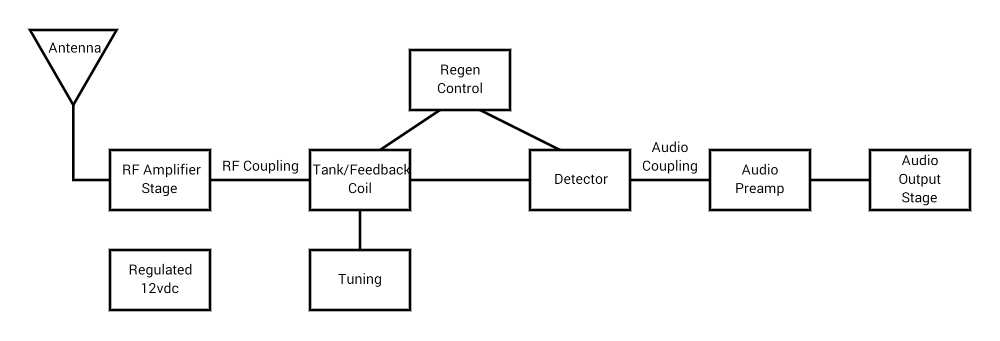
Functional blocks in my tube regen design.
I can separate the design decisions for each block, research them separately, and possibly even build and test them in stages. This is an approach that I find comfortable, after all, that is how software is made.
Bravo Dave, Thanks for sharing your experience.
73,
de N2HTT
