
Almost immediately after finishing the two-tube transmitter last spring, I began to think “Gee, wouldn’t it be great to build a receiver from scratch, so I could have an entirely homebrew station?” Apparently this kind of self-destructive thinking is a not uncommon side-effect of completing a homebrew project.
However, I believe I was influenced by a lot of discussion of home brew, regen receivers on one of the blogs I frequently read. From May 2014 through the end of September I counted 16 blog posts relating to regen receivers, most of them occurring in the month of August. No wonder my thoughts turned fondly toward building one of these fascinating rigs. I am apparently, highly suggestible.
Regens have something of a reputation among some hams as being difficult to use, but I knew in advance of ever laying hands on one that I would love it. Consider the following:
- the same detector can receive CW, SSB and AM
- they are extraordinarily sensitive
- regen designs possess a low part count -they are relatively simple circuits
- they are interactive – you have to coax the signal out of the ether. Sounds like fun.
What’s not to like?
I started looking around at circuits in early August, and at some point, I’m not exactly sure when, I came across the WBR regen design. I think I found it in an unusual way. I was looking at qrpme.com, Rex Harper W1REX’s excellent site where he sells a variety of kits and builders supplies. In particular, I was looking at MeSquares, these really great little break-apart tinned squares that make Manhattan style building a cinch. Rex has links to some example projects built with MeSquares. One of those projects, by Dave Richards AA7EE, was a beautiful WBR regen receiver. Dave’s blog posts on the WBR are absolutely required reading for anyone contemplating building one of these puppies. He provides a lot of great experiential information and links to other sources, a wealth of information. (The origin of the WBR was a QST article by Dan Wissell N1BYT which appeared in the August 2001 issue. If you are an ARRL member, (or have a lot of really old QST’s out in the garage) you can access the original article for reference. The online reprint also includes some corrections that were published a couple of months later.)
It also didn’t hurt that Dave’s Manhattan style building technique approaches that of fine jewelery. The work is just beautiful. Something to aspire to.
The WBR regen is itself an interesting and unusual design. One negative trait of regens is that since they use an oscillator to create the regeneration, connecting it directly to the receiving antenna can put out a respectable QRP signal on the air. (See the SolderSmoke blog post for January 19, 2015.) Not a good thing to have your receiver competing with your transmitter for attention. Many regen designs often have an additional RF amplification or buffer stage between the antenna and the oscillator, to prevent leaking the oscillator signal on the air. But the WBR solves this problem very elegantly with a passive circuit: it uses a balanced bridge for the input tuned circuit, and places the antenna connection at ground potential. Voila, little or no radiation, and a quiet and well behaved regen.

The balanced bridge input tank with center-tapped toroid
So by August I am giving serious thought to building a WBR on 40 meters. I was just on the verge of starting to acquire parts when suddenly… I did an Arduino project. Right around the end of August I purchased a Vibroplex Champion “bug” keyer from a ham on the west coast, Terry N6CW . During the email exchange surrounding the sale, Terry commented on how modern keyers don’t capture the “fist”, or unique timing of hand sent code:
“…I like the uniqueness of my sending but I am trying to figure out how to get it into a memory keyer. No memory keyer will allow one to record a hand key message…”
Terry, N6CW
Uh oh… I’m a software guy… Arduino’s cost about $25… I had to.

The Digital Fist Recorder
There then ensued a software and hardware project that lasted until December: The Digital Fist Recorder. Using an Arduino, an SD card, and purpose-built software, I created a device that will record and play back exactly what you send with any hand key. You will find mention of it in prior posts – there is a YouTube video demonstration. I haven’t written too much about it here, because the last week of November and first week of December was spent writing a detailed article about the project which was accepted by QST. It should show up sometime in the next 12 – 18 months, watch this space for details.
Anyway, thoughts of building a WBR were not forgotten, but definitely back-burnered. Nothing soaks up all available time like a project involving software. But finally, around mid-November I started collecting the parts: T68-6 toroid, MPF104 JFET, MV104 varactor diodes, all readily available and inexpensive on eBay. The rest are all commonly available junk box parts. I started to work.
Dave has published complete schematics for a modified version of the WBR that he built for 31 meters, using an enhanced audio section. It makes use of a single transistor preamp, and a different configuration to provide more and nicer sounding audio from the venerable LM386 audio amplifier chip. This audio circuit comes from the VK3YE Micro 40 DSB rig.
I decided to build my WBR for 40 meters, but to include the AF stage from Dave’s design. It seemed like a good idea to build the audio section and test it first. Once that was known to be working, if the completed receiver didn’t work the problem would then be isolated to one of the more mysterious portions of the circuit, narrowing down the possibilities for trouble shooting.
In general, I lay out my Manhattan style circuits so that they more or less look like the schematics. As I laid out the AF stage, I kinda soldered myself into a corner, winding up with a somewhat more messy layout than I had hoped — but carefully verified against the schematic. Full of optimism, I hooked up an audio source, fired up the circuit, and… nada. Silence.
Oh no, this was the easy, familiar part. After a careful re-reading of the documentation and the schematic I finally saw it — Dave’s schematic showed the pin-out of the LM386 in “dead bug” position, upside down. I had put the part in on a MePad, right side up. All the connections went to the wrong side of the chip. Okay, I pulled the chip off the board, flipped it, and soldered it back upside down. Beautiful audio poured out of a very unlovely looking board. I put this board aside while contemplating next steps. We’ll call this AF Stage v1 on Board #1 for future reference.
It’s dead, Jim
After a few days, I took a fresh board and build a new AF stage. With the experience of the first build behind me, the second board was much prettier, and worked first try.

AF Stage V2
Now to move on to the receiver portion. The general plan for laying out the receiver was:
- audio in the back left corner,
- input tank in front on the left,
- JFET detector smack in the middle,
- regen oscillator front right,
- and power regulation right rear.
I worked from the antenna connection and the power connection towards the middle, building in an organic fashion. That means I was running out of space around the regen oscillator, and things were getting a little cramped. Again, the layout wasn’t what I hoped for, but I verified each connection and it looked correct. I connected the detector output to the beautiful AF Stage, applied power and… silence.
I probed with my scope looking for any signs of oscillation around the transistor, but there was nothing. Not a peep. I put the board away for a few days while I thought on it. This was AF Stage v2 and RF Stage v1 on Board #2.
First try.
The following Sunday I had some time available, and I decided to build another receiver section on a new board. I had lots of parts; unless the part is prohibitively expensive I always buy a few spares in case I wind up inadvertently destroying one while building. As with the AF stage, benefiting from the experience of building RF Stage v1, RF Stage v2 was laid out more neatly, and the relationship of the parts to the schematic could clearly be seen. This one would surely work. There was no AF stage on the board bearing RF Stage v2, so using every alligator clip patch cord I could find, I hooked up AF Stage v2 (Board #2) to RF Stage v2 (Board #3).

Every alligator clip lead I could find.
Apply power. Experience disappointment. Whatever the problem was, it didn’t have anything to do with the layout of the circuit.
The next day, Monday, I decided to reach out to Dave and ask his advice on how to troubleshoot the problem. I sent him an email explaining the problem and asking his advice, and was surprised to get a response almost immediately suggesting I give him a call. I was delighted, but suddenly a little nervous — I had better review the documentation before I called, so I wouldn’t sound completely lost. That decision did the trick. It always pays to re-read the documentation.
The 3904 NPN transistor, in the familiar T-92 plastic case, has a standard pin-out of collector-base-emitter in this pattern:

2N3904 NPN Transistor. Note base lead in the middle.
The MPF102 JFET, has a gate, source and drain. The source and drain are interchangeable, and the gate roughly corresponds to the base in a bipolar transistor. The MPF102 also comes in the T-92 case, and without carefully looking at the data sheet, I assumed the pin-out to be drain-gate-source. It is not. It actually looks like this:
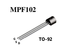
MPF102 JFET. Notice the gate lead on the left. Not in the middle.
I had made the same mistake on both boards: the JFET was installed rotated one lead. Instead of presenting a reasonable impedance in the feedback of the oscillator, it was essentially an open circuit.
I got on the phone with Dave, and explained my discovery, and he confirmed it to be the likely cause. We went on to have a very enjoyable conversation, and that evening I re-installed the JFET in each board, and got oscillation with both. Hooking up AF Stage v2 to RF Stage v2, power and an antenna, I was rewarded with my first received audio. But not very loud.
During our conversation, Dave had mentioned that many builders have encountered the lack of sensitivity in the WBR, and suggested adding about 0.2uH inductance by in the form of a T37-6 toroid with a few turns on it. Too much inductance would not be a good thing, inviting the possibility of broadcast band interference bleeding through. I decided to wind 9 turns on a T37-6 form (about 0.3 uH) and add it to RF Stage v2 (Board #3) and give it a try. It worked beautifully. True, I could hear a trace of BCI now and again if the RF gain was full up, but backing it off a bit cured it. Dave’s describes a BCI trap filter in his blog, but I didn’t feel the problem was severe enough to warrant the additional circuit.
So at this point I have several working parts to what amounted to two regens. I decided I wanted to use RF Stage v2, (Board #3) for the regen that went into an enclosure, but it did not have an AF stage. My best looking audio stage was on Board #2 with messy RF Stage v1. After studying Board #2 carefully, I decided it would not survive the surgery to excise AF Stage v2.
Back on Board #1 languished the ugly but functional AF Stage v1, all by itself. It would take some daring precision work with my sheet metal shear, but

Precision sheet metal shear, for delicate work.
I cut AF Stage v1 off on a section of board, and bolted it to Board #3. My first regen is a duplex.

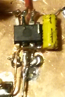
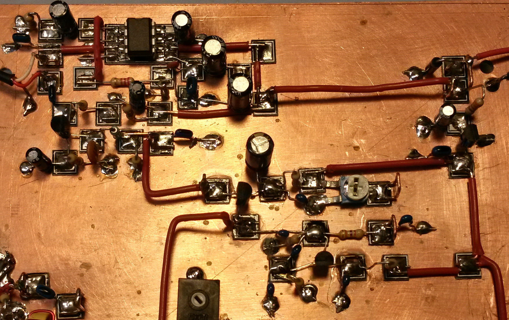
40M WBR interior
I has to wait a week or so for some parts to complete the installation in an enclosure. I found a nice steel box, and ordered a bunch of 10-turn pots from China. I opted not to include a speaker — room for the speaker would dramatically increase the cost of the box, and I will be using the receiver connected through a T-R switch anyway. The finished product looks and sounds great. I am so impressed with the way this regen receives CW and SSB; it is a snap to tune and a delight to use.
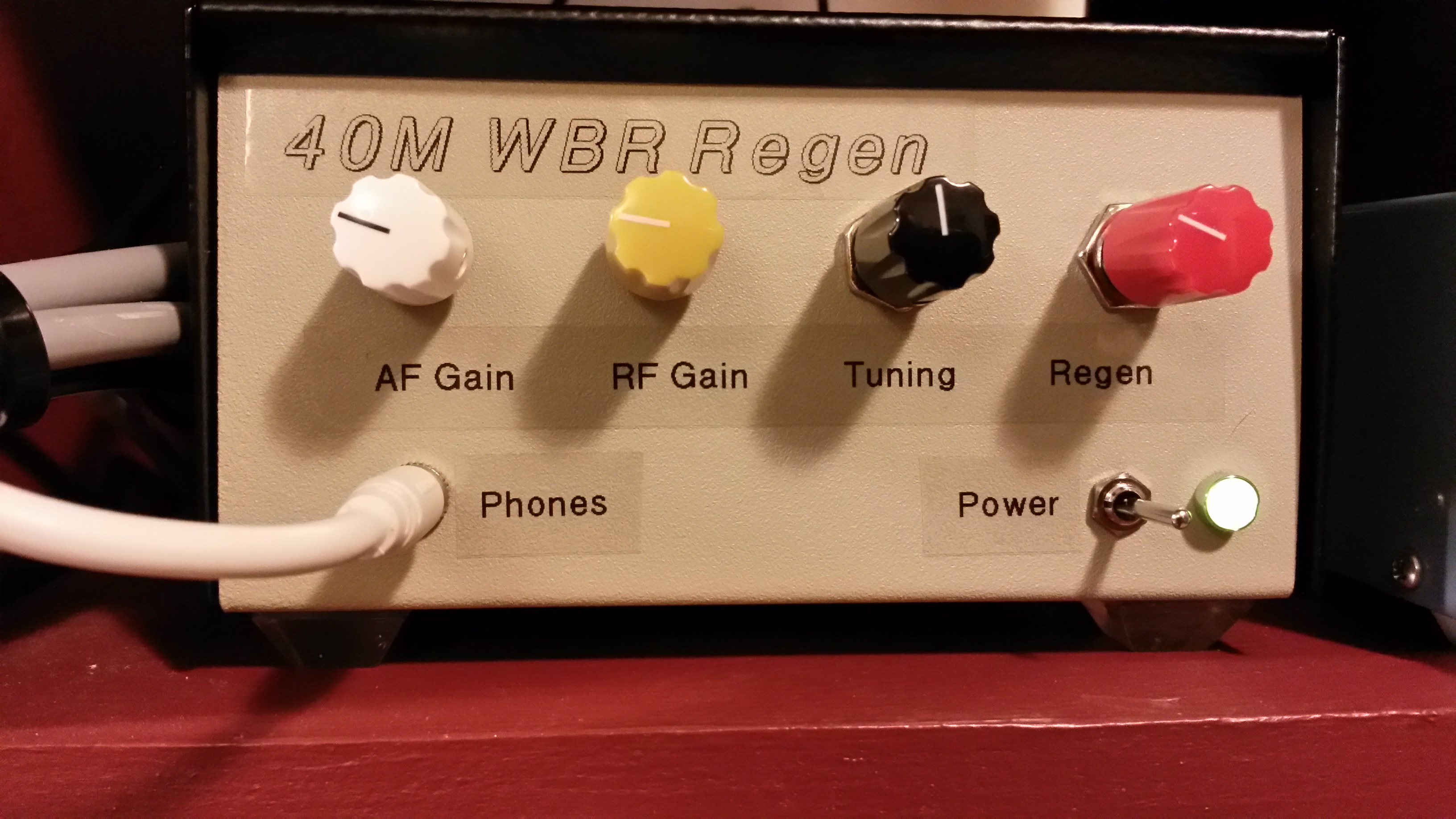
The 40m WBR installed in its case, on the operating desk.
This has been a real watershed project for me, my first home brew receiver. And it provided another opportunity to enjoy the camaraderie that makes the makes the ham community great.
What about Board #2? I’ll tell you what happened to that in the next post.
73,
de N2HTT

Pingback: N2HTT Builds His First Receiver – A WBR Regen! | Dave Richards AA7EE
Hi Mike…I just found you page via Dave Richards site. I tried building the WBR last year…I almost got it to work but not quite. I could get audio and some signals but never loud and I didn’t notice much in the way of have any noticeable regeneration……I took it apart and rebuilt it three times. Unfortunately my work space is very limited. Not like it was years ago when I had a dedicated shack. Now, I’m living on a boat and am using my small table as a workbench…not the best…. very difficult even trying to solder. Maybe one day I’ll dig it back out and give it another try. Glad you were able to get yours working. 73/72 Neil WA4CHQ/qrp
Hi Neil, hope you get a chance to give the WBR another try sometime. I had all sorts of issues with mine until I finally got it to work, including some fairly silly mistakes along the way. Perservere, you’ll get it going. You mentioned low audio, and when I first got my circuit working it was pretty deaf. Adding a small amount of inductance to the input, 0.2uH or so, really made a big difference. I do hear a little BCI occasionally, but turning down the RF gain usually handles that. Good luck with your project, and thanks for the comments, perhaps we will meet on the air sometime. 73 Mike N2HTT
Hi Mike….Oh, I’ll give it another try. From watching the youtubes, it seems like a pretty slick little rx. As I mentioned, my biggest issue is not having the space like I had before where I could be working on a project and walk away from it and not have to move everything everytime I did that. Now when I’m done for the day, I have to put everything away. I’m glad you have yours working. Regens are nice radios. The only one that I built was a one tube regen that I built back in the early ’70’s. I’ve built other rcvrs… a few DC and a few superhets…..for some reason the WBR stumped me! hi….Thanks for the encouragement. An will look for you on the air. I mostly work 40 and 30m….cw only. 73/72 Neil wa4chq
We might very well bump into one another on the air, 80/40/30m QRP is pretty much all I do 🙂 73 Mike