
Update:
My understanding of inter-electrode capacitances was incorrect as described originally in this post, and I wanted to set the matter straight before I confuse someone else: The small inter-electrode capacitances in the tube present less and less reactance as the signal frequency increases. At RF frequencies, this reactance becomes small compared to the plate resistance, and provides a parallel path for the signal to bypass the plate resistance and head straight for the exit. So less and less of the signal is actually amplified as frequency increases.
Although triodes do suffer strongly from this effect, it can also be a factor in other tube types. Using a choke instead of a resistor for the load tends to offset this effect: as frequency increases the choke’s reactance increases, which increases the gain of the stage. This offsets the loss of signal to the lower reactance path provided by the i-e capacitance. More on this in the next post about a pentode RF amp.
Having said that, I know I feel better. Now back to the original post. Ignore any nonsense about shorting to ground.
After finishing the Cubic Incher, I have returned to working on the first stage of the Low Voltage Tube Regen (LVTR). I have been using Grayson Evans book, Hollow State Design, and trying to nail down the computations for the grounded grid amplifier. I’ve alluded to the fact that the results so far have been less than spectacular, and I will return to that in moment. First I want to tell you about how these calculations have re-acquainted me with an old friend, and caused me to view it with new respect.
The computations needed to determine the components of the grounded grid amp involve repeated use of of several familiar formulas: Ohms law, the reactance of a capacitor or inductor, parallel impedances, etc. as well as some new unfamiliar ones, like the stage gain of a tube amplifier as a function of the load and plate resistance. All of these require correct units as well, engineering notation is a must (where all values are expressed as a mantissa and power of 10 that is divisible by three, you know milli, centi, kilo, mega etc.). This is especially important for capacitors. Picofarads are 10-to-the-minus-12 Farads, converting to nanofarads and microfarads continues to confuse me and I always have to check my work with some online conversion page.
Anyway, back in the day (before smart phones) I have had a series of programmable scientific calculators. I always preferred the HP line of calculators, particularly because the sported an advanced feature called Solver. Solver was great – you entered an equation, which the calculator would parse for you and display all the variables as soft entry keys. You’d enter all of the known values, and press the soft key to compute the unknown. If the equation was not deterministic, Solver would use some iterative numerical method to approximate a solution. How slick is that?
Well my HP calculators are now all gone. And I can hear the welling chorus (mostly my kids) saying: there’s an app for that. And there are; you can emulate the old programmable calculators of yore, or find purpose-made apps for doing most of the calculations I need. But it just isn’t the same on a phone. One real problem is that my phone is almost always low on charge, maybe I need a new battery. There is something comforting about a calculating device that will run on 4 penlight batteries indefinitely.
Although I have no HP calculators kicking about, I do happen to have a couple of TI graphing calculators: a TI 83Plus, and a TI 82. The newer one was my son’s in high school – required for a math course and abandoned when the course was over. The 82 I picked up at yard sale for $5. I never cared much for the TI calculators – thinking that the user interface was clunky compared to that of the HP’s. However, it’s what I have available, so I spent a week programming the functions I needed on the TI 83.
My respect for this calculator has soared. Once you get the hang of the UI (reading the manual at least once is a requirement), it really is a very well thought out and capable calculating machine. I wrote several small programs that allow selection of what you want to calculate, and then prompt for the dependent variables. Homebrew Solver. It took some effort, but I am very pleased with the result.
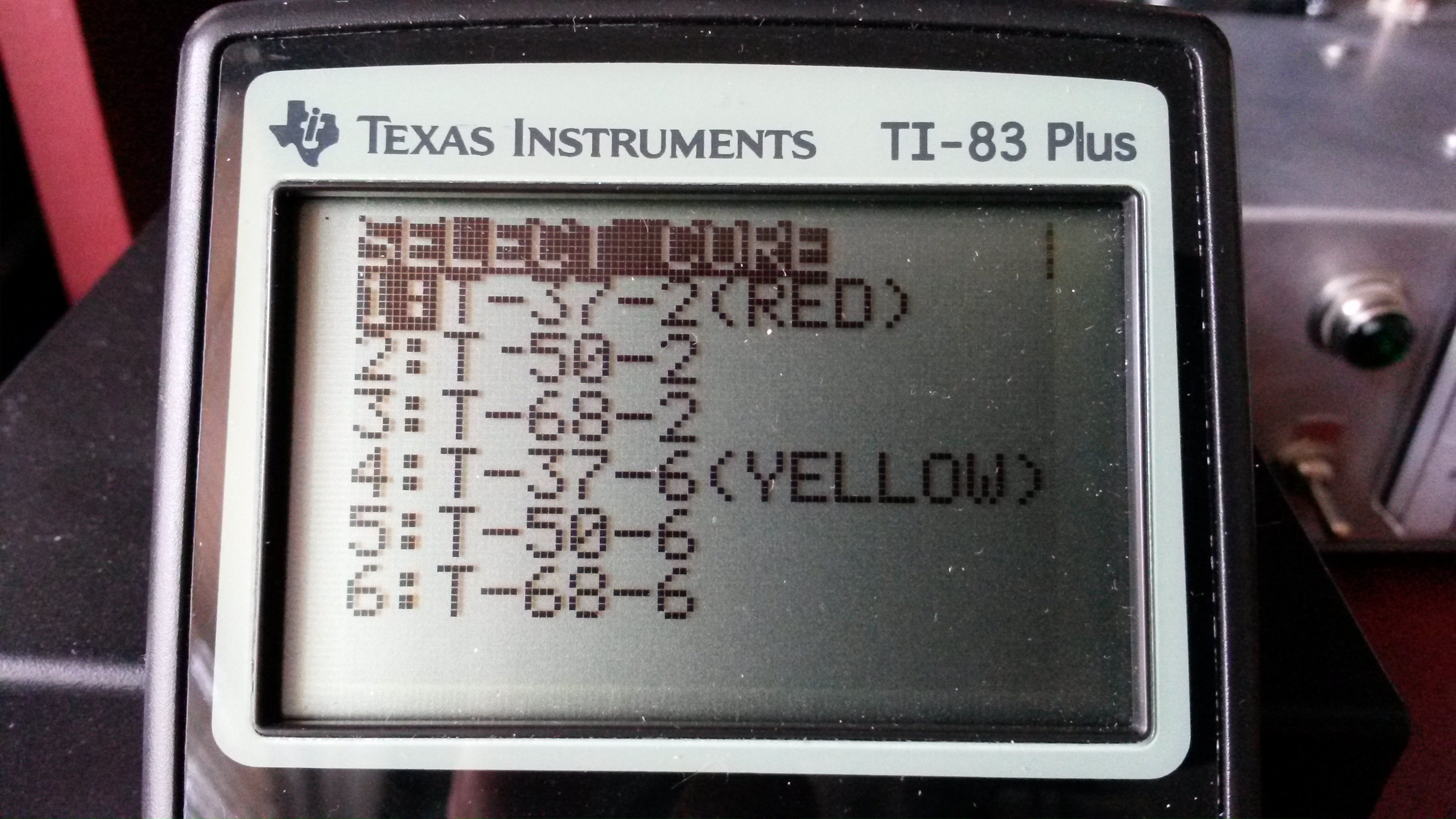
First menu of TOROIDS program: pick your core.
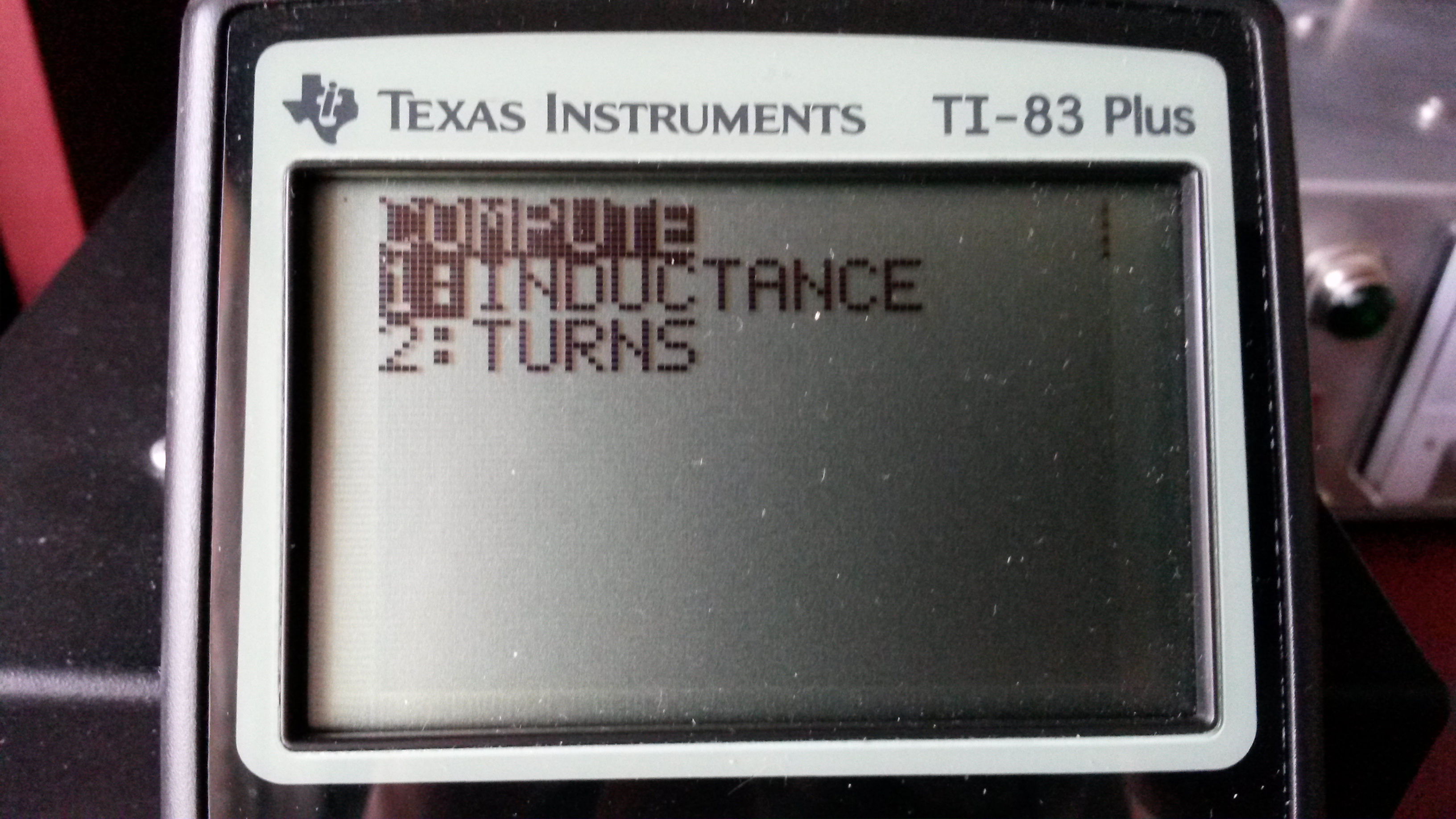
Second menu of TOROIDS program: what do you want to calculate?
It also turns out that the TI 83 has a Solver function that works very similarly to that of the HP calculators, but only allows storing one equation at a time. It’s in the MATH menu, on the second page, where no one is likely to stumble across it. Who knew?
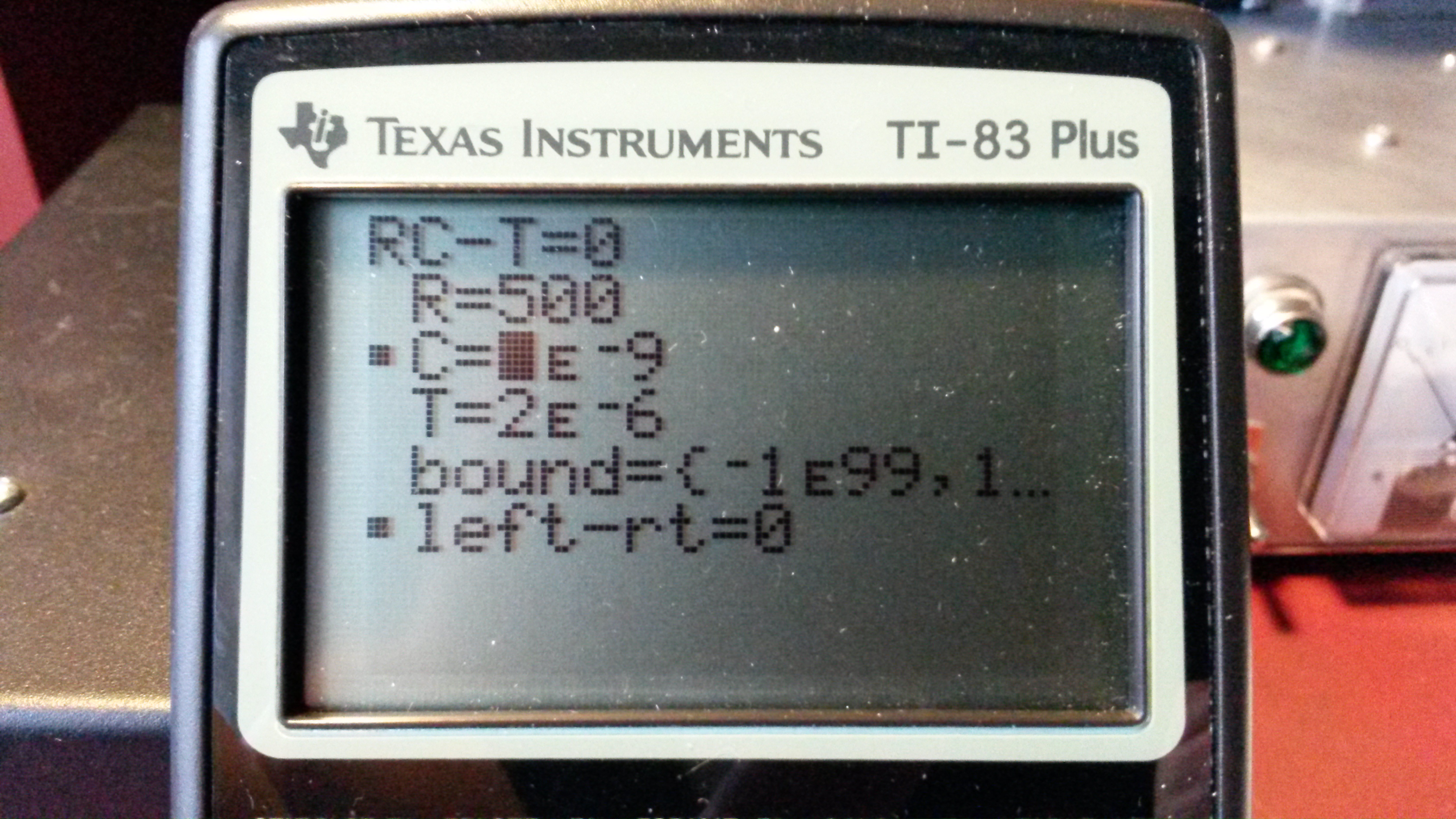
TI-83+ Solver function, working on T= RC (time constant calculation)
Armed with my new computing friend (which handles engineering notation, and complex impedances transparently by the way) I proceeded to munge through the triode design examples in “Hollow State”, until I felt I had gotten everything figured out, and all the components for a grounded grid amplifier picked out. My design parameters are:
- Class A operation, near unity gain
- 12 volts on the plate
- broad band operation over a range of 0.5 – 30 MHz
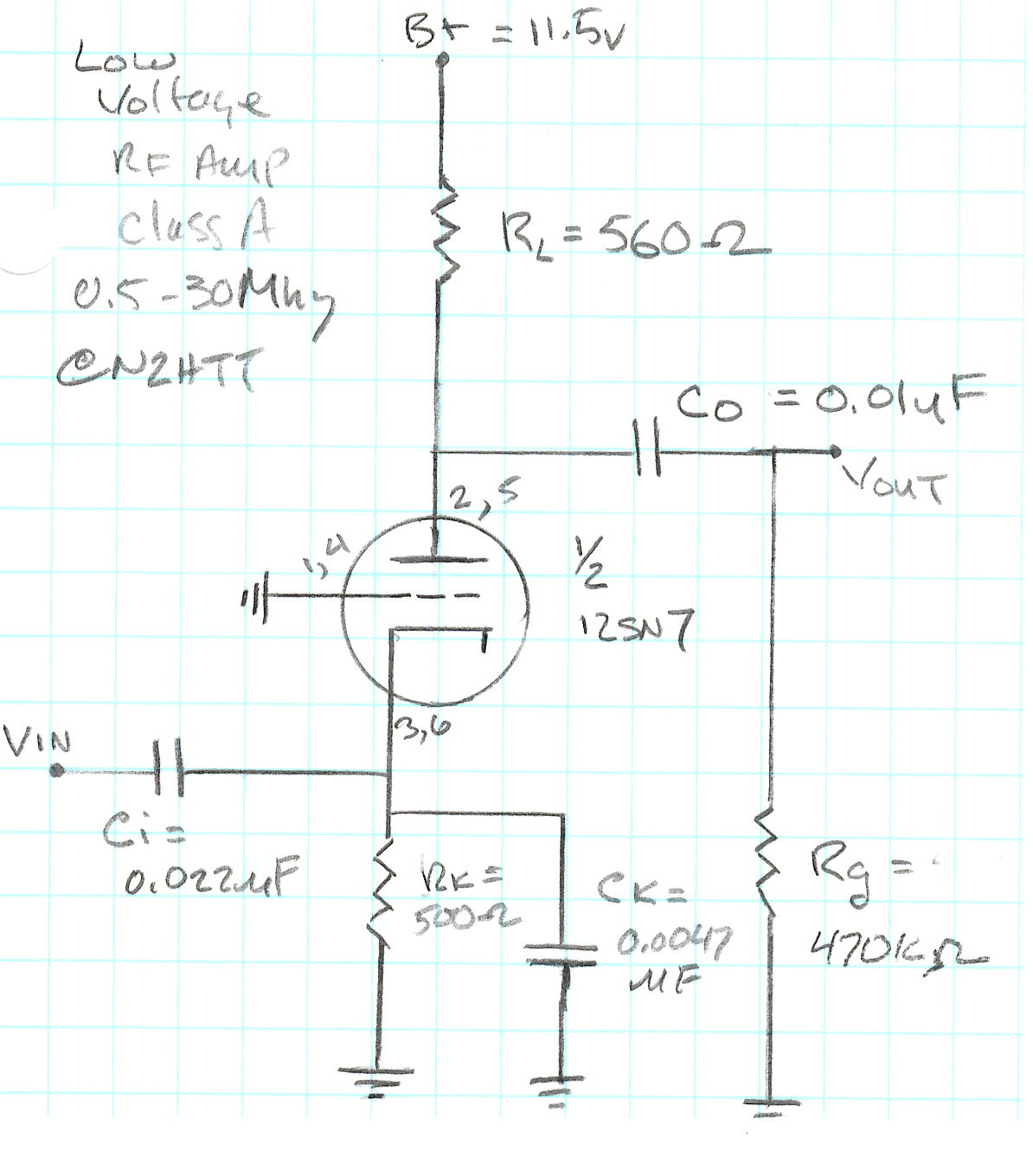
My schematic for the triode grounded grid amplifier.
In going through the calculations, and looking at the characteristic curves supplied from the data sheet of the 12SN7, it was clear that I was going to be operating the tube in the fringes of its design domain, but it looked like it could be possible.
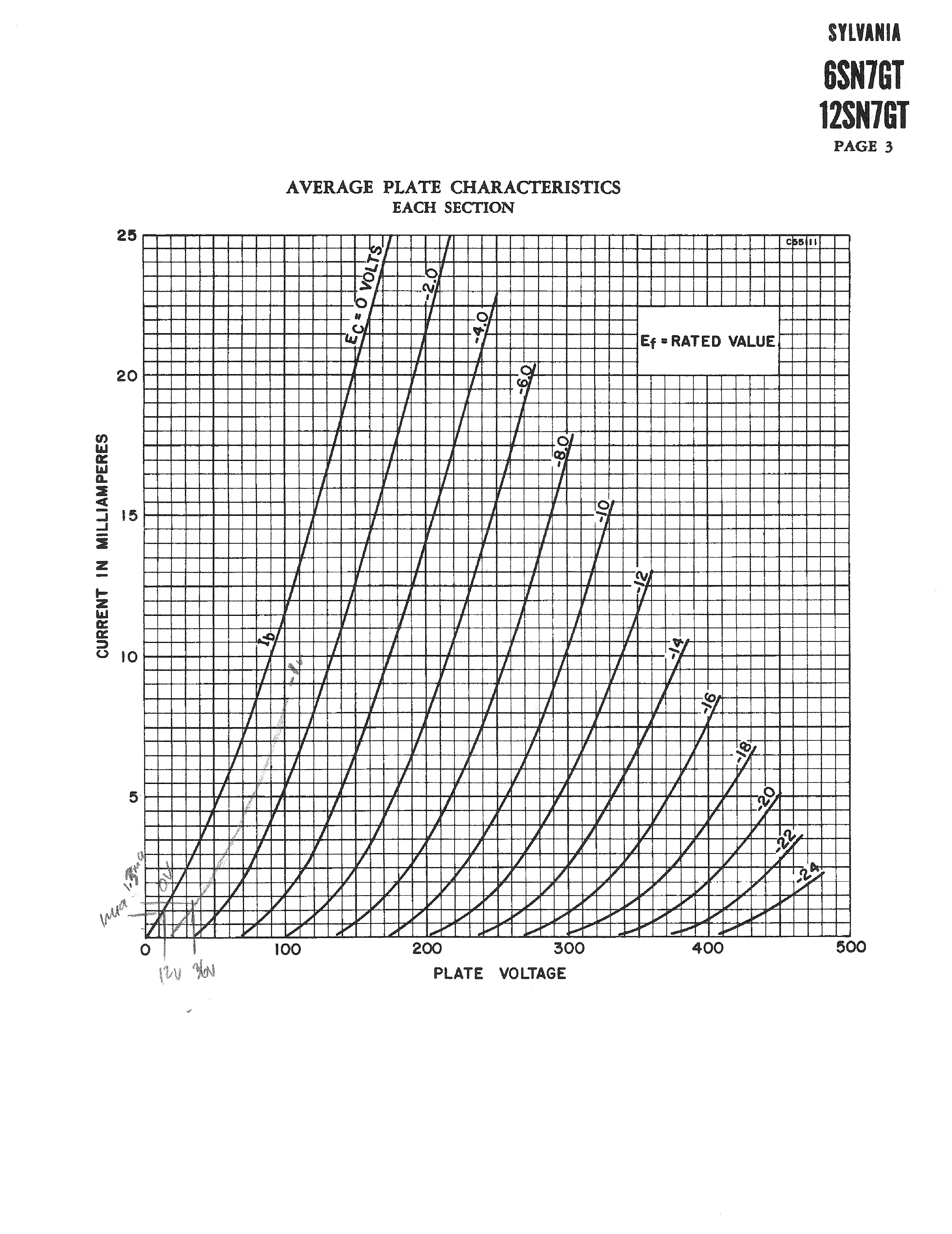
Plate characteristics of the 12SN7. Notice my design lurking in the lower right corner.

Detail of plate curves, showing my design in the weeds.
In order to test this circuit, I built a “breakout box” test bed for an octal tube base. This fixture allows me to make all of the connections by screw terminal, no soldering required. Also, I can separate the + voltage to the heater and plate, to allow trying higher plate voltages.
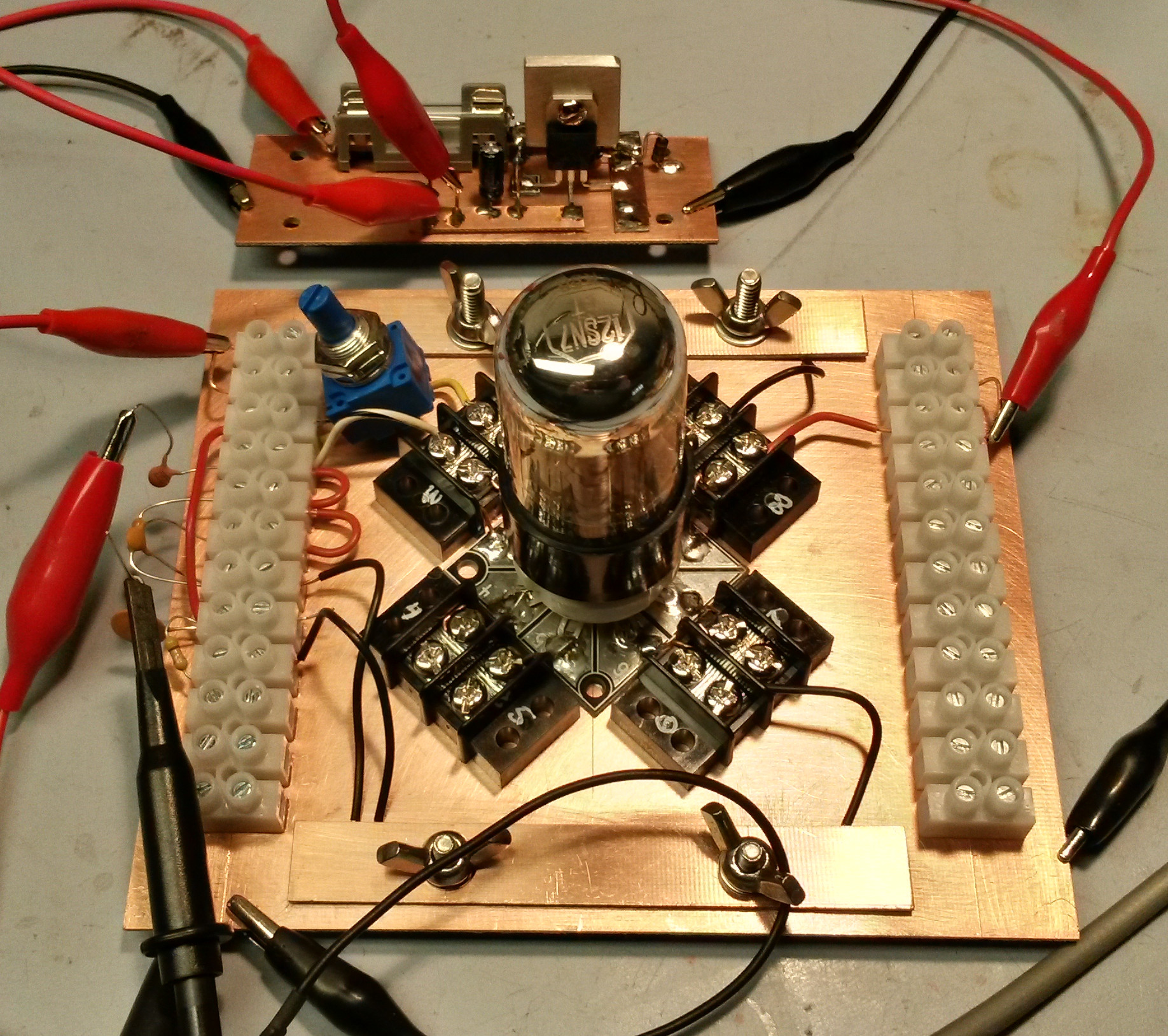
Octal tube base test bed.
I hooked it up, and….. Not so good.
Originally I was using a little signal generator (an Elecraft kit Note: they no longer make the single band version I have, now it does 20, 40 and 80.) intended as an S-meter calibration tool, outputting 50 microvolts at 7.040Mhz as a calibration point for an S-9 signal. It was just disappearing in the output. Okay, maybe a bigger input signal would let me see what was happening a little better.
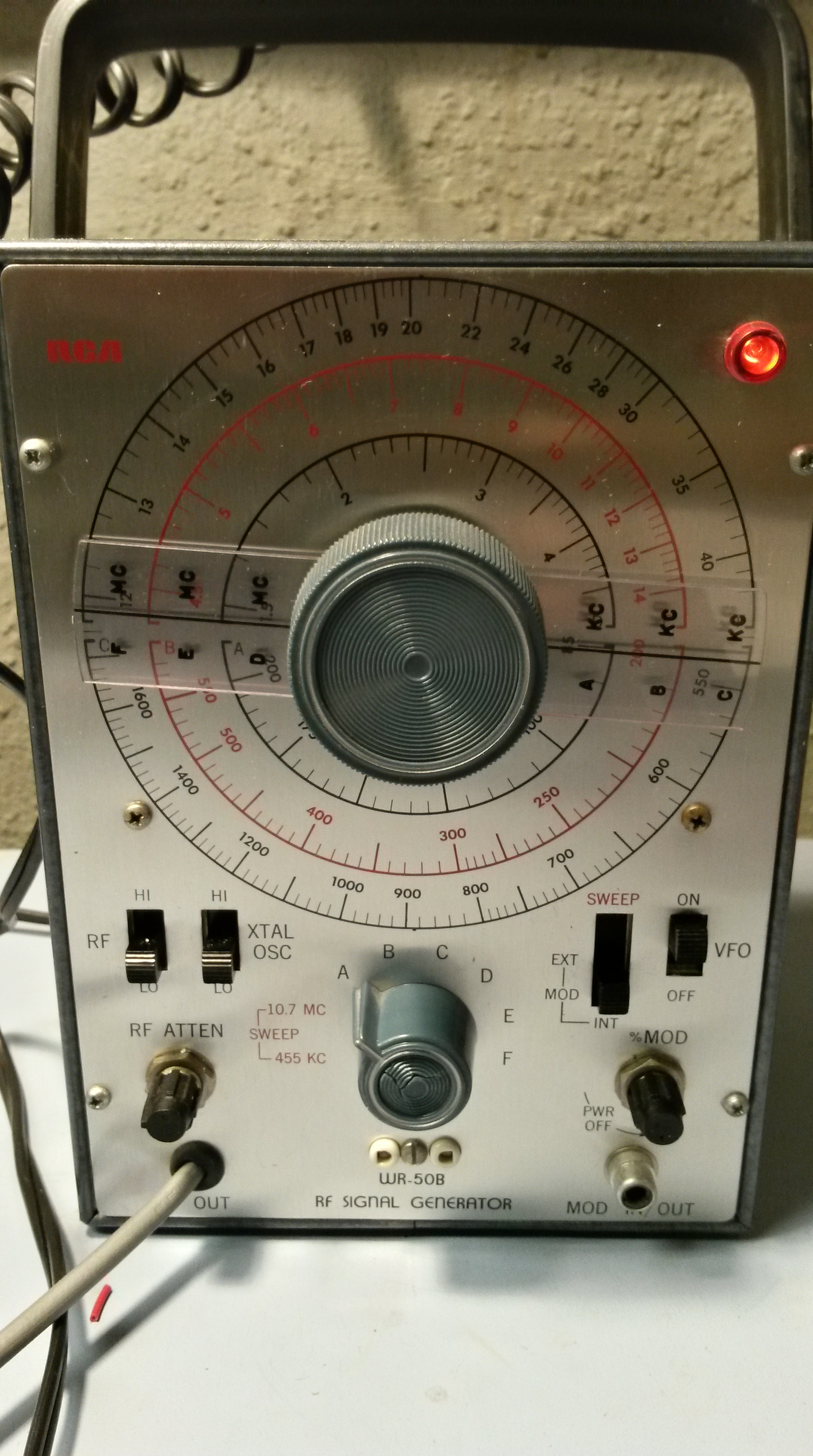
Vintage RCA signal generator.
I have a vintage RCA signal generator that I picked up at the Bring & Buy club auction a few years ago. Perfect for this application. I set it up for around 7 Mhz, and a 5 mv signal (about 40 over S-9, a really loud station) and tried again. You could barely see a little signal in the output, again way down. Despair began to creep in. What was I doing wrong?
I thought maybe you can’t get any output with 12 volts on the plate. I connected 4 9-volt batteries in series, giving me 36 volts, recomputed the load and cathode resistors, and tried again. Pretty much the same result. Going back to “Hollow State”, I re-read not only the triode examples, but some of the earlier material on tube characteristics, and this time through I caught it.
Triodes have a few pF of inter-electrode capacitance, in the case of the 12SN7 I think the total is about 5 pF. At audio frequencies this has a really large reactance, and very little signal leaks to ground through that path bypasses the plate resistance. However, at RF frequencies, that reactance drops to about 1 k ohm or less, and a lot of the signal is lost. To paraphrase “Hollow State”, that’s why triodes may lousy RF amplifiers, and you should use a pentode instead. I missed that on the first go through. Okay then, I should be able to test that hypothesis – I put the plate back to 12 volts, and set my signal generator to its lowest output frequency, around 85 kHz. Wow, output abounds. I replaced my load resistor with a 10k pot, and dialed it in to get unity gain – you can see the result here:

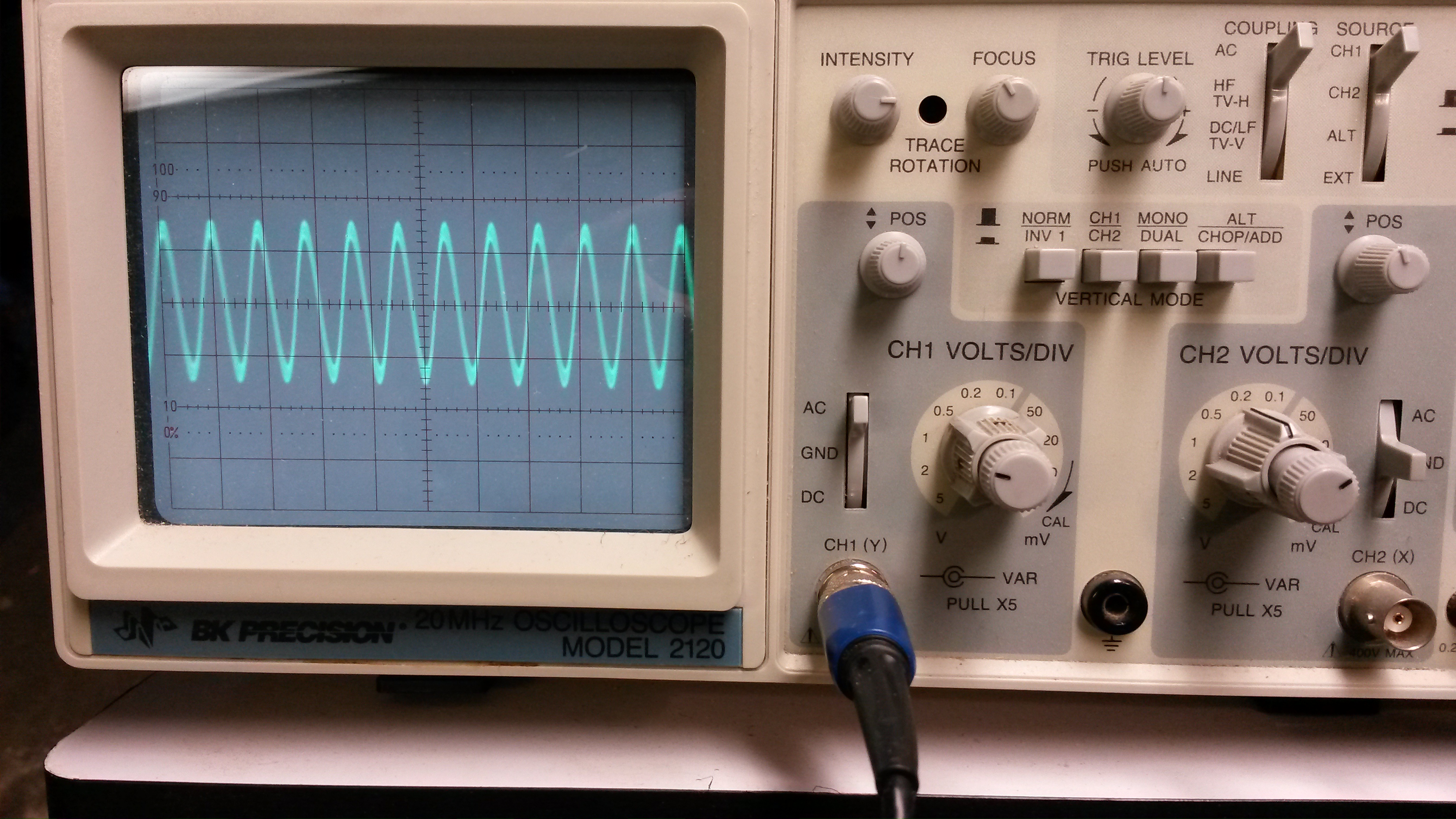
Input from signal generator at about 85kHz
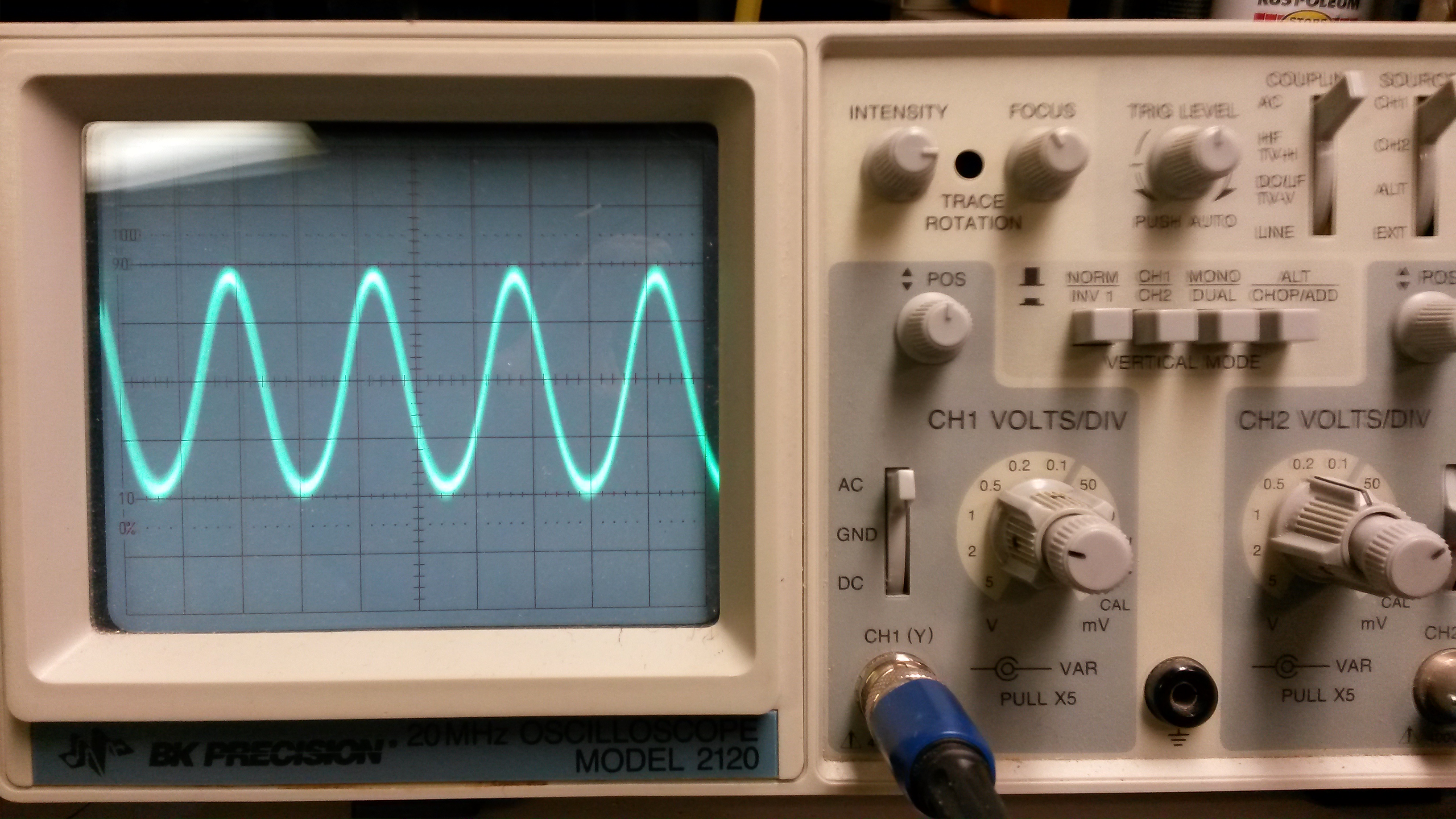
Output from grounded grid amp at 85 kHz, with 12 volts on the plate.
My calculated value of the load resistance was low – I got 560 ohms, but the value on the pot was 2k. I guess the calculated values are really just a starting point, and you have to experiment a bit to get them right.
So, if the problem was the tube response in the RF, I should be able to see the good result disappear by shifting back to an RF signal input. I changed the generator to output the 7 MHz signal again. I had to adjust the timebase of the scope, and the gain of the signal generator because the signal was a bit smaller at 7 MHz, but everything else was left the same as the 85kHz trial. But this is what I now saw, before and after, with 12 volts on the plate:
Input to the grounded grid amp at 7 MHz
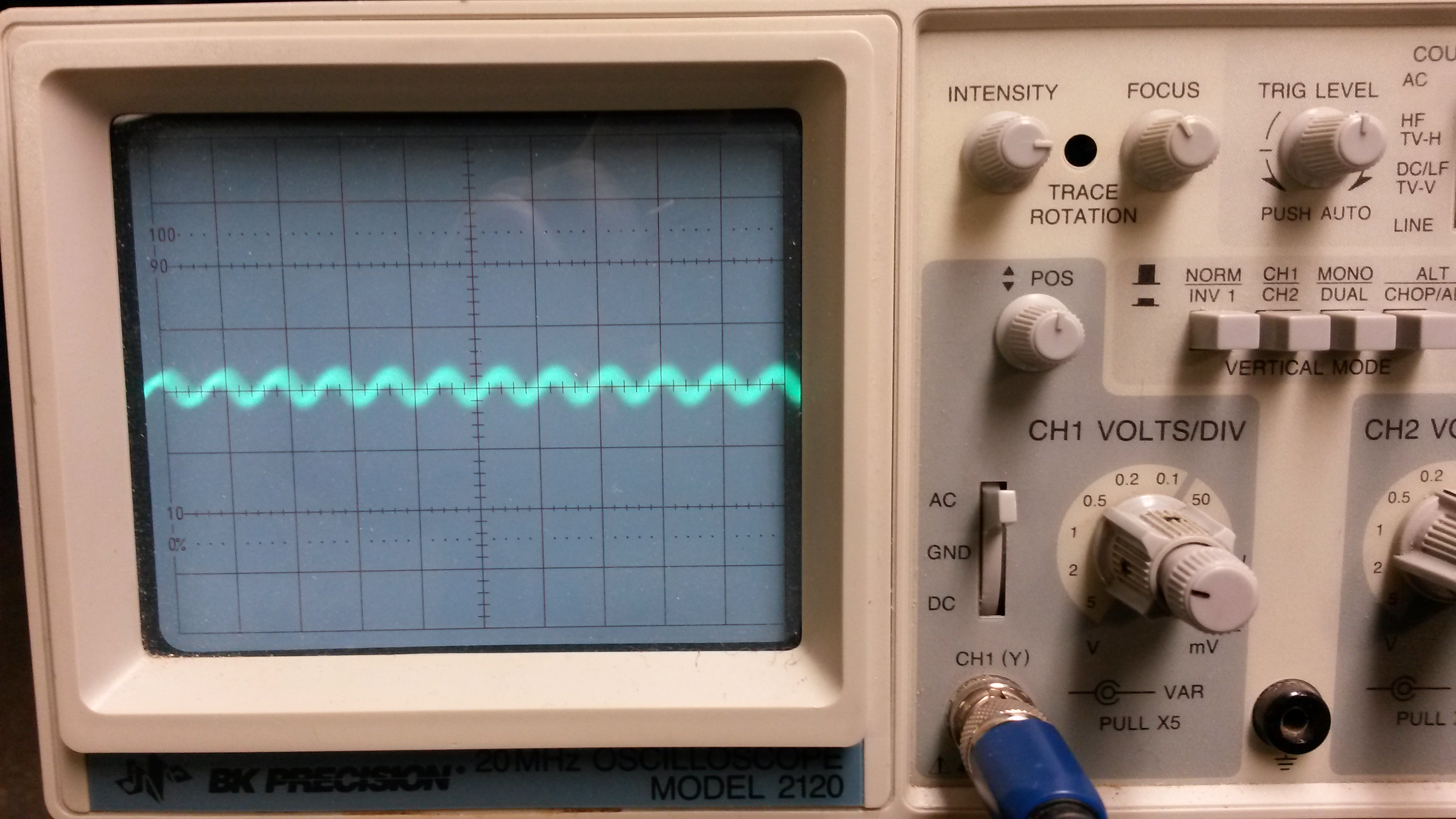
Output from grounded grid amp at 7 MHz, 12 volts on the plate.
The triode was eating my signal. It is not the right tube for the job.
I have found a space change pentode, a 12EZ6, that is made for use with 12 volts on the plate. Looking at the curves and data for the tube, I will be working smack in the middle of the design domain instead of on the fringe. I found a couple on eBay for about $3 each, and while I am waiting for them I can try to figure out the circuit for a pentode. It’s a bit more complex, and I may try to use a choke instead of a resistor to couple the output, since that reputedly works better for broad-band RF stages.
And in the meantime, I may just build something solid state, to keep my confidence up.
73,
de N2HTT
