
I’ve had a little ham radio down time, as this relentless winter rewarded me with a late winter virus that laid me low for a few days. But, back on my feet and at the bench again, with some new experiments for the low voltage tube regen (LVTR) and other projects.
As I described in the last post, the original LVTR plan of using half of a 12SN7 dual triode as an initial RF amp stage is a non-starter, because the inter-electrode capacitances of the triode become a problem at RF frequencies. Hollow State Design shows instead several examples of RF stages using pentodes, which exhibit less of the capacitance problem. I decided to try one of those, and set off to eBay to go shopping.
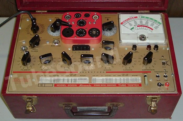
The 12EZ6 “space charge” tube seems like the ideal candidate for this task. Designed to run both the plate and the filament from 12 volts, my requirements fall smack in the middle of the tube’s design parameters. This makes it much easier to estimate the component values needed in the circuit. I quickly found several sources for the tubes, and purchased a couple for about $4 each, shipped. When they arrived, they tested strong on my Hickok 6000a tube tester.
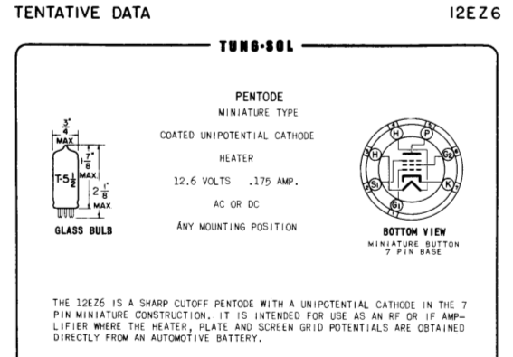
12ez6 data sheet
I decided to try an impedance coupled, common cathode broadband RF amp with the 12EZ6. The use of a choke to provide the load impedance is really rather clever: as the frequency increases, the impedance of the choke goes up, resulting in higher stage gain. This compensates for higher losses in the tube at higher frequencies. The low DC resistance of the choke allows the operation of the plate at close to the source voltage, Pretty cool for no moving parts, no?
The RF amp design worked up like this:
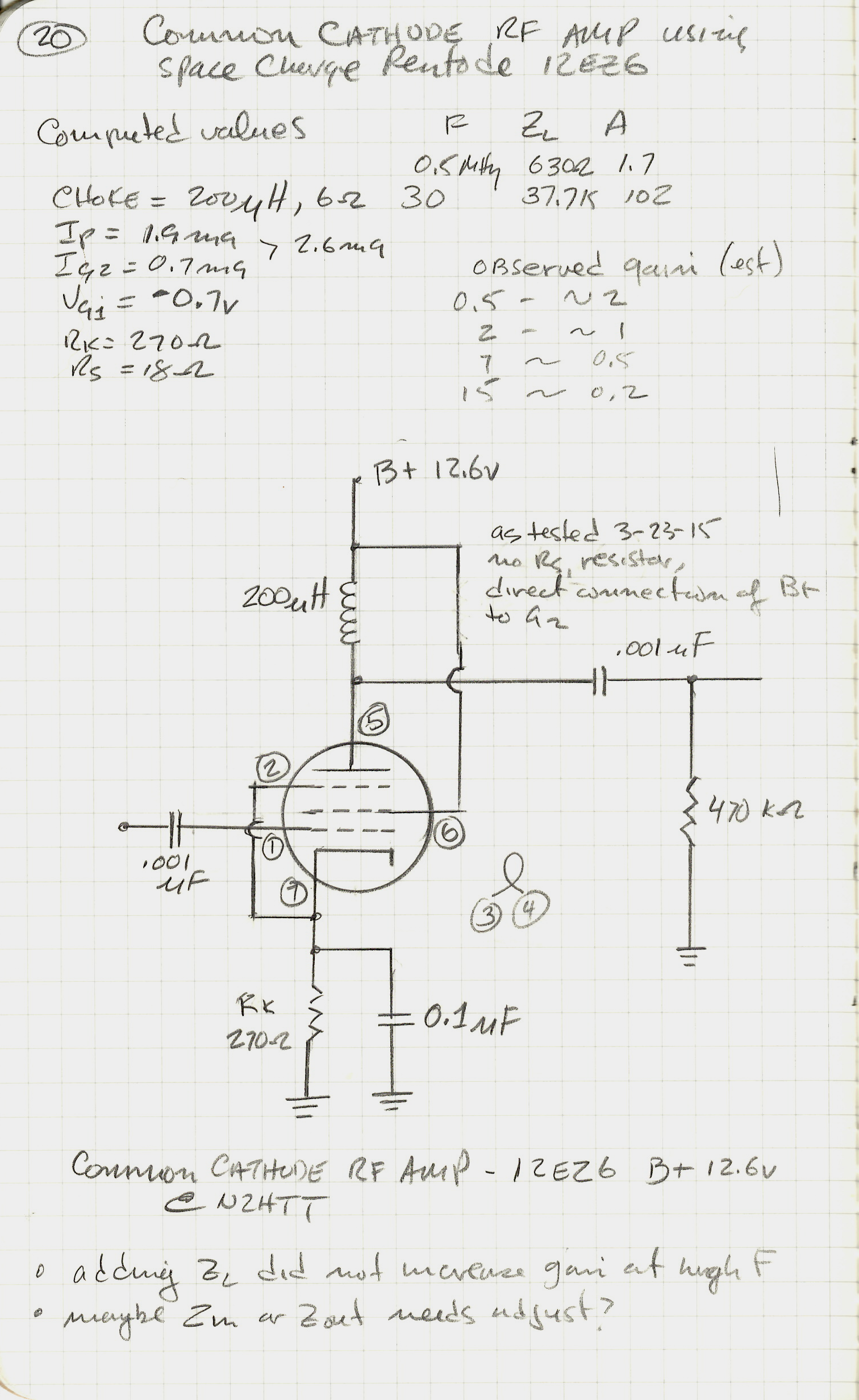
Common cathode RF amp with 12EZ6
Based on the calculations, the stage gain should vary from about 1 at 0.5 MHz to 102 at 30 MHz, Sounded promising, although value of 102 is not realistic; the stage gain at higher frequencies actually drops below 1 because of losses. I chose to use a 200uH choke, because I have a bunch of them. I also have some 2.5mH which I tried as well, but increasing the load impedance did not seem to make much difference in the output signal level, so I stayed with the 200uH part.
Since the 12EZ6 is a compact 7-pin tube, I had to put together another “breakout” board with a 7-pin socket. These things make it very easy to lash up tube circuits for prototyping. Here`s what the circuit looked like when done:

12EZ6 on the 7-pin breakout board
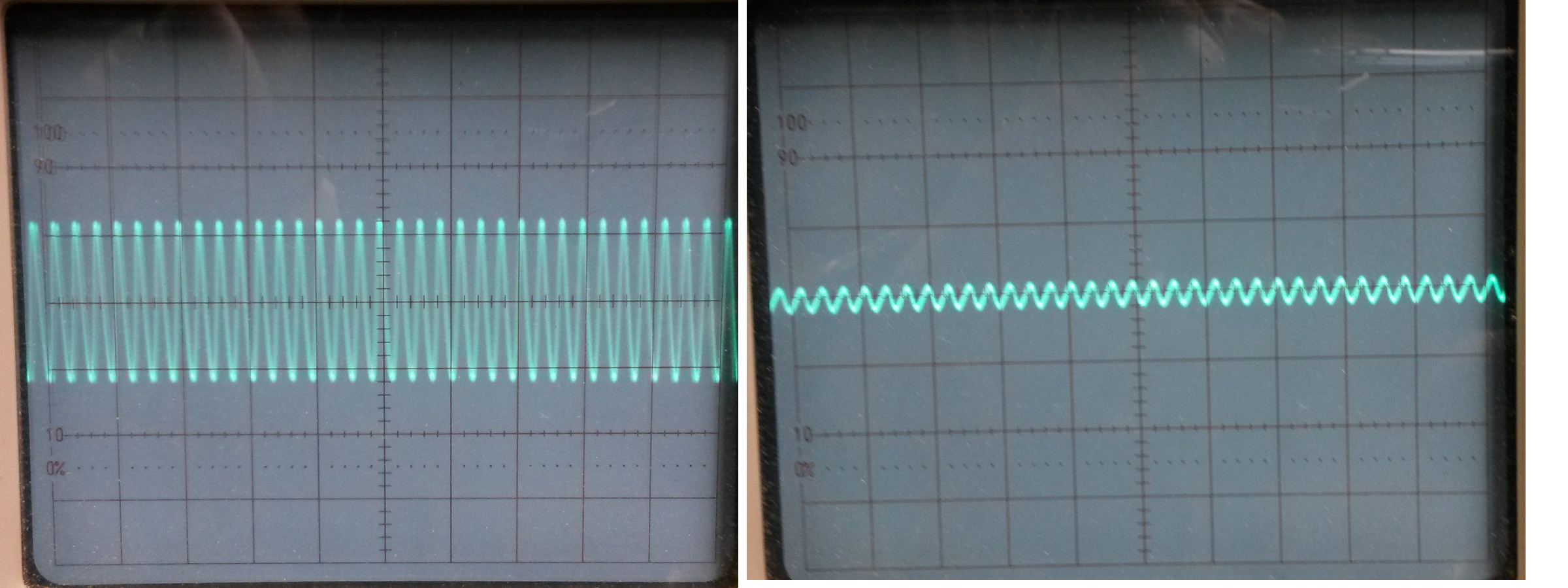
Overall it performed much better than the triode, the output waveform looks very good. Output from triode at RF looked pretty distorted. Also, the impedance coupled pentode did work better at RF frequencies than the triode did. But… still not where I would like it to be. In the following photos, the image on the right shows the input from my trusty, rusty signal generator. The one on the left shows the output from the 12EZ6 plate. Since the signal generator amplitude varies inversely and considerably with frequency, it’s necessary to compare input and output images side by side. In all of these images the settings on the scope are unchanged.
At 500kHz, some positive gain as predicted by the calculated values.

12EZ6 input/output at 0.5 MHz
At 1.0MHz, we have lost about half the signal.

12EZ6 input/output at 1.0 MHz
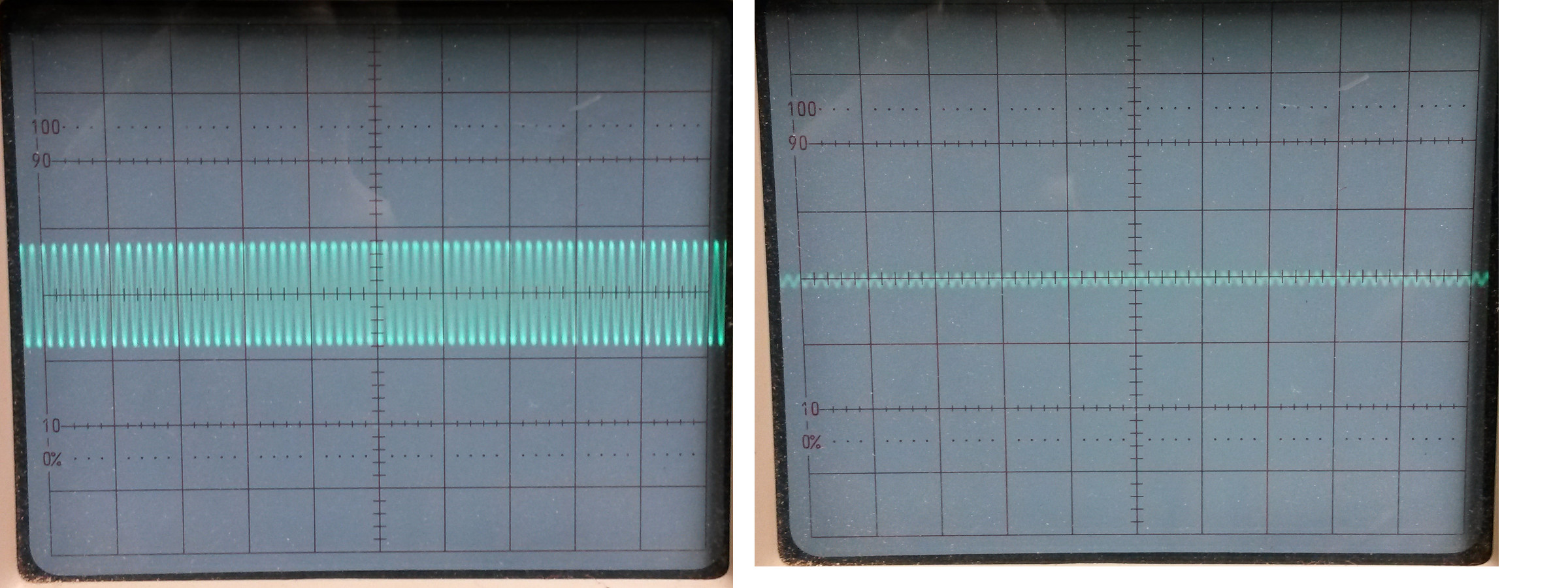
At 3.5MHz we have lost about 3/4 of the signal

12EZ6 input/output at 3.5 MHz
At 7.0MHz we have lost about 7/8 of the signal
12EZ6 input/output at 7.0 MHz
At 14MHz, what signal?
12EZ6 input/output at 14.0 MHz
It doesn’t look like this configuration is a candidate for the final design of the LVTR.
Of course, I’m wondering if it is possible to do better. I haven`t tried a grounded grid circuit yet with the 12EZ6 – I don’t know if there is any reason to avoid these using a pentode. I haven’t found any examples of this circuit yet.
Another possibility would be to used tuned coupling. These circuits use a tank for the load impedance, tuned to the frequency you wish to pass. The tube capacitances become part of the tank capacitance, and so are tuned out. Could this explain the popularity of TRF (tuned radio frequency) receiver designs in the 20’s and 30’s?
Originally I had thought I wanted to avoid this approach, wanting a broadband, un-tuned first stage. But, thinking about it, I expect to need to have changeable, plug-in coils for selecting the band of operation, Why then not have a tuned “pre-selector” circuit in the RF stage? Maybe a bandswitch that selects inductances for the tank of the RF amp, along with an adjustable cap?
More research is needed along these lines, so experimentation with the 12EZ6s will continue. In the mean time I have some other projects in progress, and I just heard from Dave AA7EE about a single tube LVTR based on the 12AL8 space charge tube. Lot’s of good stuff to think about!
73,
de N2HTT
