
My recent foray into the world of software defined radio, the SI5351 based 3 Band VFO (3BVFO), has been a fun project so far, but I have to observe that since it is mostly software, it is mostly acting like a software project. That is, every time I think I’m finished, something new comes up, or I think of a better way to implement it, and we’re off to the races again. So although I have some hardware projects waiting on the bench, this last week I found myself once again wrestling with Arduino and teensy, little displays.
This iteration started with comments from Joel, KB6QVI and Jason NT7S, who both graciously tried out my sketch and offered feedback. The behavior they reported caught me by surprise, because I absolutely did not see it on either the Arduino Mega 2560 or Uno boards with my little SSD 1306 OLED display.
(My incognizance was not at all unusual; I have worked in the software business for quite a while, and experience has made it painfully clear that the developer of a piece of code is the person least qualified to find problems with it.)
Anyway, both Joel and Jason reported that the display appeared to flicker, especially if moved, and in photos only a portion the display showed up. I tried to see this effect – waving the display around, moving my head while changing the frequency with the encoder. Nada. Rock solid. I had even photographed the display and got the whole thing, but that was using my phone, where I have no control over the shutter speed.
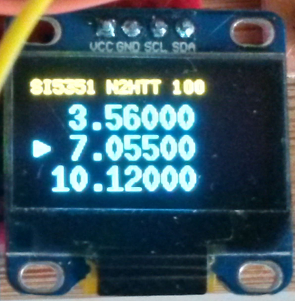
0.96″ OLED display, not showing problem
In any event, I was pretty sure that even though I couldn’t see it, there really was a problem. Since the reports of flickering seemed to start after I had replaced the Adafruit display library with Google’s U8glib, it seemed like the U8glib documentation was a good place to start looking.
As I mentioned last time, the Google library uses a somewhat different approach to painting the display, a loop instead of single display function. And, the Google library takes up much less SRAM (and much more flash) than the Adafruit code. Something different was going on under the hood, I wanted to find out just what it was.
I went back to the U8glib wiki page, and started to poke about. I found a promising looking page entitled “Details on the Picture Loop”. Since it was this looping call mechanism that seemed most different to me, that seemed a good place to start. It turns out that this page succinctly explains all the observed behavior. And it suggested a possible, immediate solution. I’ll summarize my take-away here.
Some display devices do not allow reading of data back from the device memory. For that reason, a buffer must be maintained in the micro-controller’s RAM holding the contents to be displayed. But RAM is a scarce resource on many micro-controllers. U8Glib is designed to accommodate both of these constraints.
U8glib requires the developer to create a single function that displays the entire screen. This function contains all the commands needed to paint the screen, and it has to produce exactly the same image every time it is called. Here is the display function that paints the frequency increment screen:
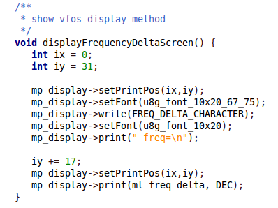
Example of display function used with U8glib
Using such a function, it is possible to divide the display into regions, and paint one region at a time. Repeated calls to the display function, once for each region, creates the entire image in a sequence of frames. You can see a nice graphical example of this at the wiki page linked above.
This approach allows the use of much smaller RAM buffers, but necessitates multiple passes to display the entire screen. It relies on the persistence of each successive image blending together to create the complete screen.
While this is very resource efficient, it has some drawbacks:
- The content displayed on the screen cannot change while the screen is being displayed. Changes can only occur between screen paints, e.g. outside the picture loop. This means any global variables referenced in the display function must not change while the picture loop is running.
- It makes true animation nearly impossible
- It can cause visible flickering, as in the case of the displays that Joel and Jason were using.
As a result of multiple passes, the effective frame rate is the frame rate of the display is divided by the number of passes to complete the image. It explains why photographs of the display showed only a portion – the camera shutter speed was faster than the display.
The solution to the problem is also built into U8glib. As mentioned in the prior post, the library comes with a dizzying array of constructors, supporting a wide variety of displays. Looking back over the include file, I now noticed several different constructors for each display type, varying the size of the SRAM buffer and the number of display passes. This places the SRAM vs. frame rate choice in the developer’s hands. You decide the critical factor, and pick the constructor accordingly.
In my first implementation I chose the constructor U8GLIB_SSD1306_128X64, that uses the smallest buffer, and the most number of passes to paint the screen. But there also is a constructor called U8GLIB_SSD1306_128X64_2X. This constructor increases the buffer by 128 bytes SRAM, and halves the number of display passes. Even with the additional SRAM, the sketch still loads on my Uno. A quick check with Joel confirmed that the flickering was much improved with the new code.
I have set up the code to default to the 2X constructor, but you can uncomment a define at the top of the main sketch file to revert to the old one.
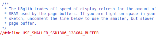
Uncomment define to use smaller display buffer
This latest version of the code is currently available on github here.
When the sketch finally settles down and stabilizes, I’ll have to decide what I’m going to use this thing for. My initial thought was a 3-band QRP CW transmitter, and I think it would work very well for that purpose. But then, I have quite a few nice little transmitters that I have gotten working now, maybe a 3 band receiver would be more useful. I’ve been working on ideas for a regen, but I think maybe a direct conversion receiver based on the SI5351 would be a good application. The receiver would be a bit more complex than a transmitter, and my understanding of the receiver circuits is less crisp. Both these factors might make for a more interesting project.
Integration of the VFO into a complete project will also likely require switching between clock sources, and possibly filters. While this could be done mechanically, it seems silly to use a computer to switch frequencies but have to manually route circuits. The easy alternative would be to use relays controlled by the sketch to do the switching under software control, but this would add more code to an already tight sketch – unless I commit to using the Mega. Then there’s space for switching, and even more features. Maybe that makes sense in a more elaborate project. There are a lot of questions to answer.
I’ll be building some of the discrete circuitry that will surround the 3BVFO on and off in the coming weeks, we’ll see how it shapes up. And there still are some tube experiments hanging out to get back to…
73,
de N2HTT
