
Back in March, around the time I had received my SI5351 breakout board kit from EtherKit, I ordered a new Arduino board to use with it. I knew I would need some kind of display, but to date had not experimented with any of the common displays used with these micro controller boards. I did a bit of Internet shopping, and finally settled on two: a tiny but attractive looking OLED display, and a more traditional 20 character by 4 line backlit LCD. All this stuff arrived before I had gotten around to building the SI5351 board, so I had a chance to play with it in advance.
I was originally more interested in the 20×4 LCD. It was big and bright, and it was easy to get going using a sample LCD sketch I found on the web. The only drawback was the number of pins — the parallel interface to the display uses 7 (!!) pins to write to the LCD, and a small potentiometer to control the contrast. That’s a lot of pins, and there were wires all over the place.
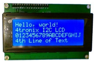
20×4 LCD display as they are found in nature
The little OLED display seemed less straightforward, but I was lucky in that the model I bought on Amazon was very similar to one sold by Adafruit, and there was a display library and sample sketches readily available. My display was on a different serial address than the normal default, but there was lots of documentation and it was fairly easy to get the example sketch working.
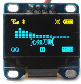
128×64 OLED display
And, the OLED only needed 2 pins plus power and ground to work. It was a huge improvement over the LCD, and once the test sketch worked, I put the big blue LCD aside and worked on my VFO sketch using the OLED display.
Of course, the magic that allows the OLED display to use so few pins is the serial bus standard called I2C. It is very popular and well supported, and many devices (like the SI5351 board) use it. It is widely available on micro controllers like the Arduinos, and can even be found on the Raspberry Pi’s, Being a bus, those two wires can support many devices simultaneously in the same sketch as long as the devices are set to different I2C addresses; this is exactly the situation in my 3 Band VFO sketch, where those two pins, (called SDA and SCL) talk to both the display and the SI5351 board.
Well after several weeks of working on the 3 Band VFO sketch (see the last few posts for details), I was pretty much done with it, but I kept wondering what I would do with that nice big blue display. Since the start of this project I have learned a great deal more about displays than when I originally purchased my two. I know now that many of the large LCD displays sold come with an I2C adapter board attached, which allows I2C serial communication (2 wires) from the microcontroller to the adapter. In turn, the adapter fans the signal out to the correct parallel pins to drive the display. These little adapter boards are referred to as “I2C backpacks”, and there are two or three types commonly used.
From my casual shopping, I found that there isn’t much difference in price between an LCD with/with out backpack, which made me kinda wish I had known about this when I made my purchase. It occurred to me that it might be possible to buy the backpack board separately, and retro fit it to my LCD display. Checking on Amazon, I found one backpack board for sale, but at around $12 it didn’t seem worth it — that was more than I had paid for the display. eBay to the rescue; I found a seller who had the backpack boards for about $2 a piece. True you had to by five, but hey, they’ll probably come in handy again some day. I couldn’t pass up the deal.
My backpack board(s) arrived surprisingly quickly. There was some simple assembly required: a 4 pin, 90 degree header gets soldered to the input pins of the backpack (Vcc, GND, SDA, SCL), then the backpack slips over the 16 pin header on the LCD display and is soldered in place. There is a tiny pot built into the board for a set and forget contrast setting. Quick, sturdy, and foolproof.
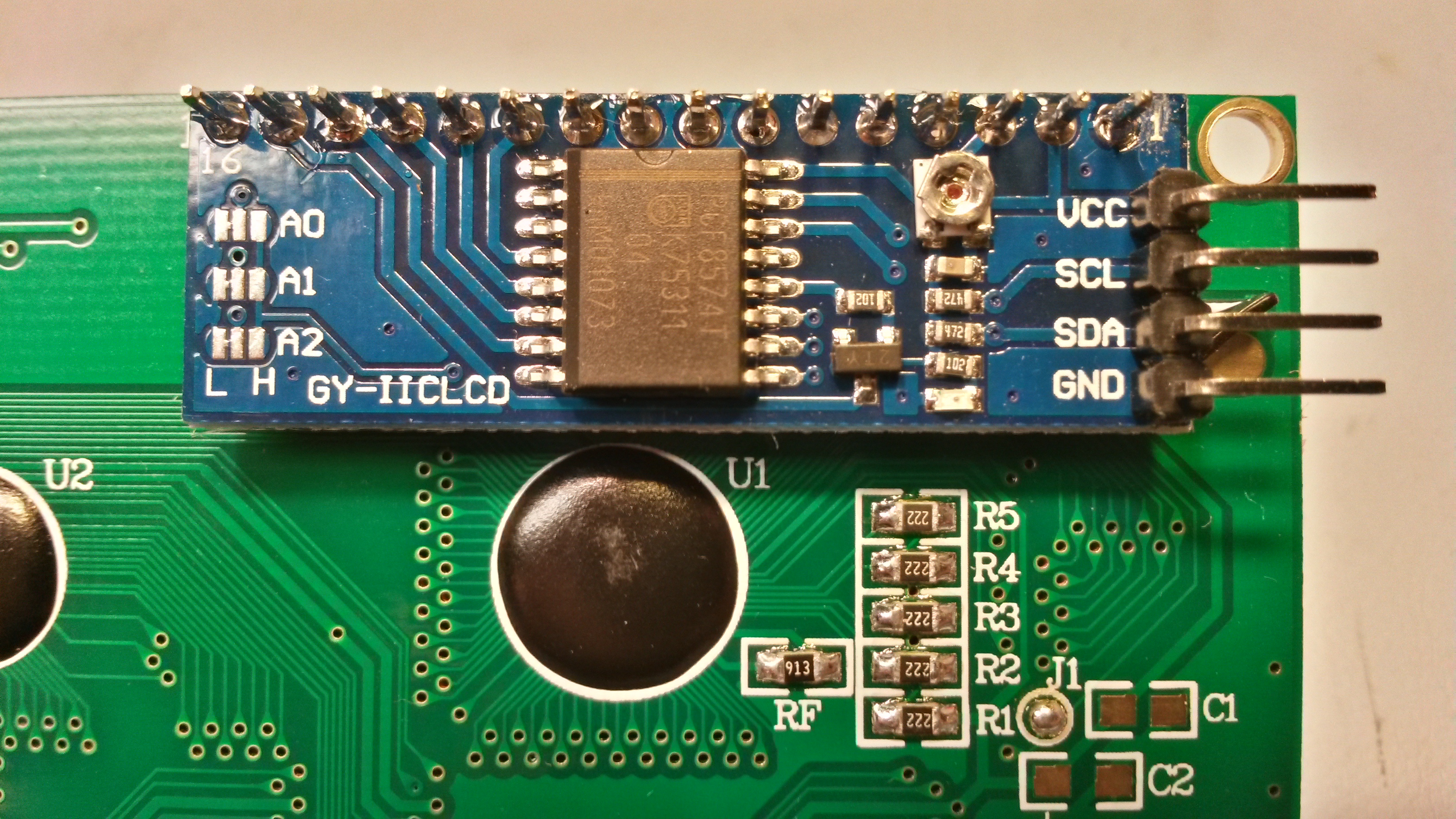
“Backpack” I2C adapter board installed on my 20×4 LCD display
Finding software to drive the my new serial LCD display was easy as well. Some quick Google searching lead me to this excellent wiki site with complete details on interfacing the I2C backpack to the LCD display. It was here that I learned about the three types of backpack board. I identified mine, and got all the details on how to configure the display library.
The display library was recommended by the wiki site is the LiquidCrystal_I2C library written and maintained by F Malpartida. I have come across many references on the net to this library, it is apparently the one to use. The code is distributed under a Creative Commons license, and is available from BitBucket.
The test sketch worked immediately, and I was talking to my new big blue display over only 2 wires. The next step was to integrate it into the 3BVFO sketch. My class design for the 3BVFO is intended to allow easy expansion to new displays or libraries as I come across them. This is accomplished by using a base class which defines the high level methods needed to talk to the display. The main sketch uses these methods only, and is unaware of how they are implemented. The first version of 3BVFO had one child class to run the OLED display using the U8glib library. To add LCD support, I derived a new child class for the LCD and LiquidCrystal_I2C library. The fact that this code handles the display in a completely different fashion than the OLED class is hidden from the main sketch, which could care less. The beauties of object oriented programming, and encapsulation!

VFODisplay class hierarchy
There is a difference however, in programming a microcontroller as compared to a full size computer. In an Arduino sketch, memory is limited, and every byte counts. So an object oriented program intended for a full sized computer would contain code to handle all display implementations, and your program would create the display object you needed and ignore the rest. In a micro controller, we don’t want all that unnecessary code laying about, for the display we’re not using. The solution to this problem is a programming feature that is familiar to anyone who has coded in the C or C++ languages: compiler pre-processor directives.
Pre-processor directives are instructions to the C++ compiler, which inform it on how to manipulate the source code before it is compiled. The one pre-processor directive that everyone has seen is the #include command. This command instructs the compiler to find the file named after the #include, open it, and insert the text from that file, byte for byte, at that spot in the program. This is a huge advantage — imagine having to cut and paste code from all the #include files manually into your sketch before it would compile.
There are a large number of pre-processor commands, and I’m not going to delve into all of them here. But there are just four that I use to enable easy switching between the display types in the sketch. They are #define, #ifdef, #else, and #endif. With these commands it is easy to create blocks of code that are conditionally compiled – that is, only added to the sketch if the pre-processor settings require it.
The general structure of conditionally compiled code looks like this:
#define SOME_SYMBOL
. . .
#ifdef SOME_SYMBOL
do_this();
. . .
#else
do_that();
. . .
#endif
In the example above, because the symbol SOME_SYMBOL is defined earlier in the code, the block of lines starting with do_this(); will be compiled and the lines between #else and #endif will be discarded. If the #define was commented out (or removed):
// #define SOME_SYMBOL
Then the lines starting with do_that(); will be compiled, and everything between #ifdef and #else is discarded. Note that it is not that the lines not chosen are skipped – they are actually removed from the program. And any flash or RAM memory that might have been used by them is not used.
In the main file of the 3BVFO, right at the beginning, you will now find two sets of #defines
One set compiles the OLED display code, the other set compiles the LCD display code. Choose the display you want by commenting out or deleting the #defines for the unwanted display. Of course, only two defines, one or the othe pair, should be defined. Any other combination will result in compile errors, or at very least confusion.
Here’s what is looks like when we are using the OLED display (the default setup):
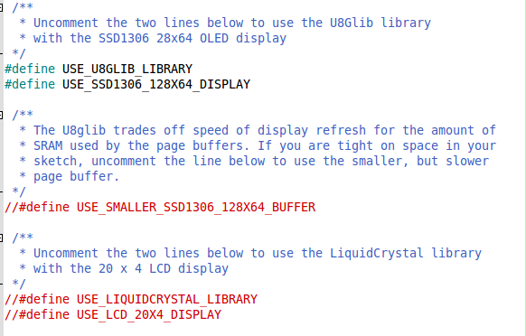
#defines set to compile OLED display code
and here is what it looks like if we want to build it for the 20×4 LCD:

#defines set up to compile LCD display
One additional benefit of the new LCD display support: with the LCD, the sketch will now run on an Arduino Leonardo or clone. These tiny boards have 32 kb flash memory, but 4 kb is used for a special flash loader programming, leaving not enough flash for the OLED display version. But the LCD code is much smaller, and it fits the Leonardo just fine.

3BVFO on 20×4 LCD Display
The latest 3BVFO sketch can be found on github here.
This may be it for the Arduino part of this project. I’ll have to start building some circuits around the 3BVFO and turn it into a real radio.
73
de N2HTT

Hi N2HTT,
You are doing some great work with the si5351 breakout board here. Have you thought of using only one CLK output of the SI5351 for the VFO and assigning a start frequency to the same clock output when switching the band ?? like it is done in single Clock output Chips like AD9850. This way you can use the other 2 Clock outputs for BFO and a tone generator. This way you can utilize the available resources better. Just a thought.
Cheers
de VU3DES
You are quite correct – check out the work of Tom, LA3PNA – he has a sketch that does just that. His blog is at https://la3pna.wordpress.com/
When I did the sketch I was thinking more of driving a QRP CW transmitter, so I didn’t need a BFO. It would be quite easy though to modify my sketch as you suggest.
73,
Mike
Also, this way you can include more bands in the VFO than 3.