It’s the height of summer, and we are enjoying a week’s vacation at the alt-QTH in New York’s beautiful Southern Tier. The weather is warm and dry, with occasional afternoon thunder showers keep everything green, and the pace is slow and peaceful. I usually bring up lots of radio projects to occupy my time, and this year was no exception.
I have always been very interested in portable QRP operation, and have been building out a couple of portable kits for that purpose. The most recent features the MTR-4B trail-friendly rig, combined with a SOTABeams 30 foot fiberglass mast, all of which fits easily in a day pack. I have long been a fan of end-fed half-wave (EFHW) antennas, and have a couple made up on 40 meters – with a small tuner these wires can be used on multiple bands. They require only one point of support, virtually no feed line, and are lightweight, good performers.
Just a couple of weeks ago, I came across a blog post by Michael, G0POT, where he describes his experience building a trapped EFHW for three bands, 20m, 30m, and 40m. This antenna can be used without a tuner on those bands, which is a hiking plus – one less piece of gear to carry. The key to the antenna’s success is a 1:60 impedance transformer, or unun, which can be built in a small box. This becomes the rig-end termination of the antenna. Michael provides links to PA3HHO’s blog, with good pictorial instructions on how to wind this unun on a ferrite core. The resulting antenna is lightweight, needs no additional accessories, and performs well – it has become my portable favorite.
Now we come to the vacation story. I bought two toroids to make the unun, and still had the second one with me. I also have an old 1:4 balun built from a kit that I never use. Sitting on the deck looking for something to do, I decided to re-purpose the box and fittings from the balun to house a second 1:60 unun. These things just seem too useful not to have a spare on hand.
Well no problem, I brought tools and materials to build with, but unlike the primary QTH there is no well stocked bench here. And now, with the demise of the local Radio Shack store, no handy place to pick up that odd resistor you don’t happen to have.
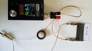
Well, the odd resistor was in fact the issue. When I had made the first unun, I tested with my antenna analyzer and a 3.3 kOhm resistor, just to verify that I was seeing around 50 ohms (plus or minus) with the resistor across the output terminals. Just a sanity check, I’m never quite sure I’ve counted the turns correctly. I did not have the resistor with me in the kit…
Of course I could just build the thing and check it out with an EFHW attached to see how it performs, but it got me thinking. If I were stranded on a deserted island with a rig that needed a 3.3 kOhm resistor to become functional to call for help, and had only typical household items available (okay so not too deserted an island. Think abandoned resort with no Radio Shack nearby) could I fix the rig?
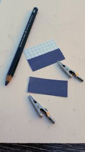
I asked myself the “what are resistors made of?” question. Precision metallic oxide films seemed beyond the realm of homebrew possibility, but what about good old carbon? We have lots of old crappy pencils lurking in the kitchen drawers, so I tracked one down that didn’t look too pristine, cut the eraser end off, and measured the resistance of the lead – only 16 Ohms, very low, but definitely promising.
To increase the resistance, I figured you have to reduce the cross-section of the material, so I tried making a dark pencil mark on a 3×5 index card and measured the resistance – about 10 Megohms. This could work.
My lovely XYL, Janette KC2LLA, supplied a very soft drawing pencil (more graphite, less clay in the lead), and I started systematically filling in dark lines of pencil lead on the 3×5 card, checking the resistance as I went. It continued to decrease to about 100 kOhms, then kinda stalled as I added more graphite. It occurred to me that the point of contact, (the meter leads) might be having an effect, so I added two alligator clips across the stripe, and the resistance dropped dramatically.
With the alligator clips in place, adding more graphite continued to reduce the resistance, but with less and less effect as the width of the graphite area moved out beyond the end of the alligator clips. It seemed to bottom out at around 6 kOhms – at this point Jan had a brilliant idea: cut the graphite area in two, and connect the two pieces in parallel.
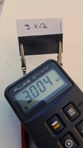
I placed the two cut pieces, graphite sides facing out, between the clips and voila – 3 kOhms! By moving the position of the clips slightly I was able to dial in 3000 Ohms pretty precisely.
After assuring myself that the resistance reading was stable and repeatable, I proceeded to build the unun. Testing with the home-made resistor showed that the windings were fine.
The unun went in the box, and a re-check with my paper resistor showed good results.
It’s unlikely that the paper resistor will find a permanent home in my test equipment, but it was a fun and interesting experiment in kitchen physics that worked surprisingly well.
73,
de N2HTT


