
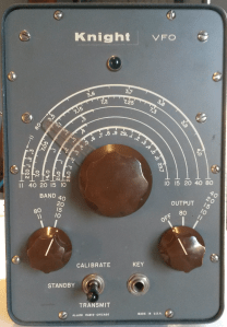
Lately, I have been completely preoccupied with the completion of my Novice station at the alt-qth (Otego, NY). It all started with participation in a vintage rig event last February, the Novice Rig Roundup. Since then I have been obsessing a bit about creating a fully functional Novice station, first by experimenting with refurbishing a transmitter/VFO pair, then the Heathkit HX-1681/HR-1680 twins.
Well, the Novice station is now complete and on the air, and later in this post I will describe the additional gear I added to complete it. But before getting to that, let’s consider the history of the Novice license that gave rise to this niche. It is a fascinating history, and actually before learning about it, I wasn’t even aware that the Heathkit gear was a Novice station. Here follows a much abridged history of the Novice license:
(The following information is drawn largely from a Wikipedia article here, but also from this page, and this page.)
Starting with the Radio Act of 1912 amateurs in the US were required to obtain a license. At the outset, there was basically only one license (well, two actually, but the conveyed the same privileges, just different method of application) and all licensees had the same privileges. This license was known as Amateur First Grade in 1912, then became Amateur Class in 1927, then Amateur First Class in 1932.
The alternate license in 1912, Amateur Second Grade, allowed applicants who could not get to a Department of Commerce field office to attest to their operating qualifications, and then later be examined by a licensed amateur to become First Grade. This license was renamed Temporary Amateur in 1927. In all cases though, the privileges granted were the same, not a novice in sight.
In 1933, the licensing scheme was reorganized by the Federal Radio Commission to comprise Class A, B, and C licenses. Here the first notion of class privilege arrived.
Class A licenses got the whole enchilada, and the Amateur First Class licenses were grandfathered into this group.
Class B licensees were excluded from certain “reserved radio-telephone bands”.
The Class C license roughly corresponded to the old Second Class licenses, with exams performed by other licensed amateurs rather than at a field office, but the existing Second Class licenses were not grandfathered in and had to re-apply because the examination had been made more stringent.
The Communications Act of 1934 created the Federal Communications Commission, the FCC we know and love today which replaced the FRC. No change in amateur licensing accompanied this event.
It wasn’t until 1951 (a year particularly important to me) that the FCC restructured amateur licensing to create six license classes, including the first Novice license. The new Novice license was restricted to CW only portions of the 80, 40, and 15 meter bands (but also phone and CW on 2 meter band), with input power restricted to 75 watts. (Power restrictions were specified in terms of input power, as this was easier to measure than output power or effective radiated power. The net result was that Novice transmitters with typical efficiencies of 30 – 50% would put out a maximum signal of around 40 watts.)
The Novice license was a one-year, non-renewable affair, it was upgrade to General or out at the end of the year. In addition, Novice transmitters were required to be crystal controlled, restricting operation to one fixed frequency at a time. This gave rise to an operating style where one would call on the crystal frequency, and then listen up and down the band for a reply on someone else’s crystal frequency, resulting in a full-duplex QSO. All kinds of quaint calling conventions arose to indicate “listening up” or “down 5kc”. I am not up to speed on these, having heard of them but never used them.
Post-war surplus crystals in the ham bands were relatively plentiful but considered a big expense for a ham just starting out (usually a teenager with a paper-route budget) giving rise to all sorts of clever techniques for moving the frequencies around a bit. Crystal munging was definitely part of Novice culture.
In 1964, the FCC and the ARRL came up with Incentive Licensing, which removed some privilege from existing licensees as an incentive to upgrade. This really annoyed a lot of hams, some of which left the hobby rather than upgrade. The term of the Novice License was extended to two years in 1967, and they lost their 2 meter privileges.
In 1977 the power restrictions in the Novice sub-bands were changed when all license classes were granted a maximum of 250 watt output in these bands, and the crystal controlled requirement was removed. (This change is what qualifies my Heathkit gear as a Novice rig.) In 1978, the Novice license was made renewable with a five-year term.
As of 2000, no new Novice licenses can be issued, but existing Novice licenses can continue to be renewed. I couldn’t find a precise number, but somewhere around 1% of licensed amateurs continue to hold Novice licenses today.
So the 1951 Novice license is the model for the Novice nostalgia genre, with restricted power and crystal controlled transmitters. I’ve tried this kind of operation, and can tell you that it isn’t easy – I have a lot of respect for any op that learned the ropes this way. Thus my intense interest in a vintage station with the frequency agility afforded by a VFO, and how I wound up with my 1977-street legal Novice rig.

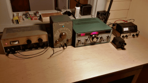
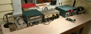
Complete Heathkit Novice Station
Centering around the HX-1681/HR-1680 transmitter-receiver twins, I have been building out my station with carefully selected vintage acquisitions, to make a state-of-the-art 1980’s Novice station. Most recently, I have added three pieces of gear.

HS-1661 Speaker
The first is a Heathkit HS-1661 desktop speaker. This unit was made to match the HX/HR twins, and puts out booming audio connected to the HR-1680. Ironically, this is the third HS-1661 I have owned; one I gave to a good friend to use with his HW-16, and the other I sold as part of the package when I sold my HW-16 station. These are really nice speakers – about 5×7 inch oval in a nice metal cabinet, with an impedance of about 4 ohms. They clean up nicely, and are impossible to kill, making them a good bet when one comes up at auction or in the classifieds.

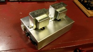
HM-2140 Watt Meter
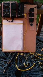
The second piece of gear is a Heathkit HM-2140 dual watt-meter. The one I found was in pristine condition, and is working perfectly, not even needing recalibration. They show forward and reflected power (or SWR) on two meter faces, and if you are a SSB op, can read in peak power as well with the addition of a 9v battery.
Finally, I decided to add a manual antenna tuner. If you read my last post, you know that I had intended to use an auto tuner with the station, but at the last moment I decided that would just be too anachronistic. I looked at the various Heathkit tuners that were common in the time period: the SA-2040 and SA-2060, but did not find anything that filled the bill. These tuners are all physically large and apparently very robust, and I don’t think people part with them. Those who do seem to want prices that do not seem reasonable to me, so I broadened my search.
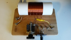
I was delighted to come across a Cubic Communications ST-3B tuner. I had never heard of this tuner (or company) before, but apparently they were around in the 1980’s and contemporaneous with my Heathkit gear, The reviews I found of this unit were all very enthusiastic. From some additional research, it appears that Cubic Communications made mostly commercial gear, and not much ham stuff, and are still around and kicking today having nothing to do with amateur radio.

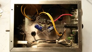
Cubic Communications ST-3B tuner
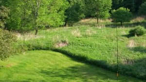
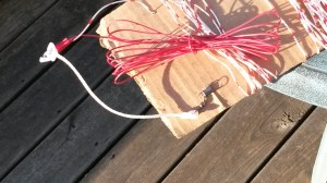
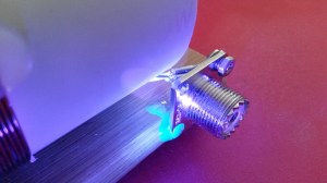
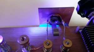
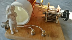
The unit I found was dirty and scuffed on the outside, but pristine on the inside, and clearly built like a tank. Some work with a Mr. Clear Magic Eraser, and using an ultrasonic cleaner on the knobs, resulted in a very presentable exterior. I will probably paint the cabinet at some point, but it’s fine as is for now. It has two charming features: the capacitors are driven by 6:1 reduction drive verniers, and if you apply 12 vdc, the meters illuminate. With the little red cube logos in each meter, the dials look like illuminated eyes, kinda cute in a spooky way. It really does load up the end fed half wave that I usually use very well.

Spooky, but cute
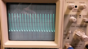
This weekend saw the running of the SKCC Weekend Sprintathon, one of my very favorite operating events, and marked the maiden voyage of my new vintage Heathkit station. I was delighted to discover that I could crank the drive level way down and operate the transmitter stably at 5 watts out, thus combining all of my ham radio favorites: CW, QRP operation, and radios that glow (at least partially) in the dark.
It doesn’t get much better than that.
73,
de N2HTT


