KX1 to the Field

This post is all about ham radio, the great outdoors and being thrifty (cheap). No computers were harmed in the making of this post.

Having recovered from blog-block after documenting the simple transmitter, I am just back from Lobstercon again this year, and filled with enthusiasm for playing outside with QRP gear. The weather in the Northeast has been really good so far this summer, a major incentive to play outside (especially after last winter.)

My primary radio is an Elecraft KX3 — very capable and very portable. At Lobstercon the KX3 was happy to operate connected to a big gel cell and an end fed half wave antenna thrown up into a tree. While at Lobstercon this year I got to talk at length to Carl WA1ZCQ and Pete N1ABS about operating en plein air, and the subject of Summits on the Air came up.

Summits on the Air, or SOTA, is an operating exercise that originated in the UK and is very popular in Europe. It is starting to catch on in the States. Lists of summits, which include everything from 300 foot hills to the top of Mount Washington, are assigned identifying codes, and points which reflect the relative difficulty of operating from that summit.

An activation consists of announcing your intention to operate from a particular summit at a particular time (there is a web reflector for this), going there, and making at least four contacts in whatever bands/modes you fancy. Other operators log these contacts, accumulate points, and qualify for awards. Good clean outdoor ham radio fun, and an great fit for anyone who likes to operate outdoors with minimal (e.g. lightweight and portable) equipment. QRP heaven.

I have been wanting to do this for a few years now and have not gotten around to it, but this year I am psyched. There are a few summits (hills) not too far from the upstate QTH that have never been activated! Probably for some very good reason that I will discover on the day I attempt one, but heck, it’s just too tempting.

So I am back from Lobstercon, and idly surfing the net looking for material relating to SOTA operating, and I come across a youtube video review of a very interesting looking product. Offered by a company called SOTABeams, and called the “Flight Deck”, it is a small plastic board with strategically placed holes and notches, which allow you to secure your miniature radio, paddle, notebook and pen to one easy to manage object. Very classy.

I know from experience that it is very easy to have your stuff go astray when you are sitting on a windy rock with wires attached while trying to listen and key and write things down. I have trouble with this indoors sitting at my operating desk, and there is no wind.

While the Flight Deck is beautifully made of high quality acrylic sheet with laser cut holes, silk screened instructions and top drawer elastics, it appears to me to have two drawbacks:

  • it is a tad expensive
  • it ships from the UK, which is most likely a tad expensive

So, in keeping with the ham radio ideals of ingenuity, re-purposing materials, and instant gratification, along with a healthy dose of reverse engineering thrown in, I present my home brewed version of this excellent idea:

Home Brewed KX1 Operating Board

Home Brewed KX1 Operating Board

I have not named this device as yet.

I started with a common fiberboard clipboard, and removed the clip by drilling out the rivets. Using the images online as a guide, I drilled pairs of holes to secure the rubber bands mid-board, and using a Dremel tool with a cut off wheel, cut generous notches to capture the other ends of the rubber bands. Happily, I already have a KX1, and a very nice Palm mini-paddle, and in about an hour had a very serviceable, if not as pretty operating desk for field QRP.

The one exotic touch is that my pen is attached to the board with genuine Kevlar twine, which I had on hand from a totally unrelated project. That sucker is not getting away, regardless of the wind speed.

So I actually tried this setup out in my backyard, with a 42 foot wire and a 16 foot counterpoise attached to the KX1, using the KX1’s built in tuner, and it worked beautifully. It was very easy to manipulate the radio and the paddle, and by the end of the test I had not lost anything. I highly recommend buying or building one of these things if you operate outdoors.

With that out of the way, I guess it dawned on my that the KX1 will be the rig in the field this year, and the next concern is powering it. I have several options already, each with pluses and minuses:

  • a 10AH gel cell battery, which would power operation for about a week, but weighs as much as a lawnmower. I get about 3 watts out of the KX1 with this.
  • a battery pack made out of 10 AA NiMH cells. Still kinda heavy, and I get slightly less power out.
  • 6 primary lithium batteries in the internal holders of the KX1, which gives about 9 volts and an expected 1.5 watts out. I haven’t tried this yet, but the lithium’s are pricey, and my KX1 seems to output a little less than nominal power.

So I started looking around the web, because I know folks have made modifications to the internal battery holders of the KX1 to allow running higher power. I found this video by K4LXY about using rechargeable Li-PO cells that produce 3.7 volts each. He made an easily reversible mod to the KX1 battery holders to eliminate 3 of the 6 cells, getting about 11 volts from the 3 rechargeable lithium cells.

Although the cells he used are initially quite expensive, they can be recharged hundreds of times making them very economical. This seems a very good solution, as it also eliminates the need for a power cable and external power source — less to carry.

In his video he shows a dummy cell made of a dowel, and another made of a fuse and holder, along with a shorting wire to eliminate one of the two 3-cell holders in the KX1. He also provided a plastic sheet over the whole thing to insure nothing would short against the dummy cells.

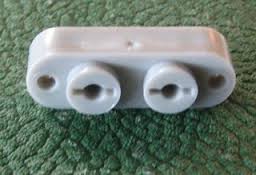
My approach is somewhat different: I have invented the perfect dummy AA cell, thus requiring no modification what so ever of the KX1. Here’s what they look like:

Dummy AA Cell

Dummy AA Cell

Here is the recipe — for each dummy cell you will need:

1 #10-24 x 2 inch machine screw
1 #10-24 nut
2 washers 3/8 inch in diameter
2 washers 1/2 inch in diameter
1 length of vinyl tubing, 1/2 inch OD 3/8 inch ID, exactly 1 3/4 inch long.

I used stainless steel hardware for mine, but actually anything would do. Except nylon. Do not make these with nylon bolts.

Assembly instructions:

Cut the bolt to 1 7/8 inch using that screw cutting hole in your wire stripper that you never use. 1/8th inch of the bolt is about two threads worth.

Cut a length of tubing 1 3/4 in long. This is a critical measurement. Try to get the ends nice and square. It may take a few tries to get this procedure down. You did buy 2 – 3 feet of tubing, didn’t you?

Place a 3/8 washer over the end of a closed pair of needle-nose pliers, and maneuver it into the tubing about a half inch in from the end, and perpendicular to the axis of the tubing. You can use the bolt in combination with the pliers to get it sitting correctly. Do this again from the other end.

Place a 1/2 inch washer on the machine screw, then the tubing assembly, then a 1/2 inch washer and finally, compressing the tubing a little, start the nut on the screw.

Tighten the nut until about 1/16th inch protrudes from the nut. This tensions the tubing enough that the nut will held in place and not loosen.

The nut side of the assembly goes where the negative end of the AA cell belongs, usually there is a spring on that side in the holder. The screw head is the “positive” end. Here is a photo with three of these dummies in an 8 cell holder:


Dummy cells in AA holder

Dummy cells in AA holder

Well there it is. Later on this summer I will get a hold of some rechargeable lithium’s and I will be good to go.

Ah, I forgot to mention: these dummy cells are guaranteed not to leak. Ever.

73,
de N2HTT


Posted in Ham Radio | Tagged , , , , , | 2 Comments

Tanked.

This post is the last in a series about building a vintage tube transmitter. All ham radio, not a smidge of Linux.

The most exciting, and anxiety provoking moment in a homebrew project is the “smoke test.” That moment when the construction work is done, the new device is sitting on the bench, hooked up to power, antenna and key, ready to demonstrate that all that planning and effort were worth it. It can be a moment of triumph, or despair.

I already knew that most of my sub-assemblies worked, as I had been testing them all along. The oscillator was putting out a nice clean signal, and all of the high voltage lines measured where they should be — I was pretty sure we were headed for a successful launch. Hooked up to a dummy load through a QRP watt meter, 40 meter crystal in the socket, and the home made tank circuit coil in place, I keyed the rig for the first time. Some good news, and some bad…

Output! Nice note, keying sounded good in a nearby receiver… but not a lot of output. I was expecting about 4 – 5 watts, a healthy QRP signal, but at the max I was seeing about 1 watt, maybe 1 1/2 watts. Now admittedly at low power the difference between 1 1/2 and 4 watts is not a big deal, but I had the sense that something was not as it should be.

I was pretty sure my home-made coil was okay. I had measured the inductance using my LC meter, and it was spot on for the coil specifications. Further, I had tested the coil mounted on the transmitter with a grid-dip meter, a device that measures resonance, and it showed the coil resonant on the 40 meter band. So it wasn’t the coil.

Well, okay, according to the excellent project manual from Ralph Taggart, WB8DQT that was the guide for this project, I should be prepared to add capacitors to the output variable capacitor in the tank circuit, if the maximum output was obtained with the plates of the cap fully meshed. That certainly described what I was seeing, so I then embarked on the aerobic exercise portion of the project.

Down two flights of stairs to my basement workbench, add a cap to the output variable, back up two flights of stairs to my operating position to try again. Lather, rinse, repeat. I was adding a huge amount of capacitance to the output variable cap, with not much beneficial effect. Without any effect, in fact. Something was really wrong here, time to return to the internet.

I read everything I could find about tank circuits. The tank circuit is what connects the output of the final amplifier tube to the antenna, and it turns out that it is a relatively recent invention in the history of the radio arts. Tank circuits became commonplace in transmitter and amplifier designs with the rising popularity of the use of coaxial cable, or “coax” to connect antennas to radios. The purpose of the tank circuit is to match the high-impedance output of the tube, to the low impedance of the coaxial cable. When the impedances are matched, the maximum amount of power is transferred from the tube to the antenna. When they are not matched, you get anemic output, and the tube glows in funny, self-destructive ways.

I found an internet article by a ham who had built a tube transmitter in two cases, the tubes in one and the tank circuit in another. He observed that when he used coax to connect the two, the output was terribly attenuated, but using plain wire to make the connection worked fine. My mistake suddenly became obvious – I had used coax to connect the tube to the tank circuit, and even to wire the tank components together! With my new found understanding of tank circuits, I ripped out all of the offending coax and replaced it with good old #14 gauge wire. Instantly, things were better:

  • the power jumped to about 2 watts
  • the output variable cap now started to have an effect. I was able to find the right amount of capacitance to add to get it to peak at the midpoint of the adjustment.

Good stuff, but I still wasn’t satisfied. 2 watts isn’t 4 – 5, I still thought there were issues. I sent an email to Ralph, WB8DQT, author of the design, and described my plight. He had be very forthcoming in helping me with some earlier questions, so I was hopeful he could guide me to a solution. Ralph replied suggesting a few things I could try to get a bit more power out of the transmitter, but basically said that it sounded like it was up and running.

While investigating one of the changes Ralph suggested, I was examining the wiring of the amplifier tube socket, and discovered that I had omitted a connection! The amplifier tube is a pentode, a 5763, and the suppressor grid pin was supposed to be grounded. I had left this connection out. Adding this connection made a big difference! I was now getting about 3 1/2 watts from my vintage 40 meter crystal.

FT-243 Crystal

FT-243 Crystal

At this point I figured I was finished, and would have been, but for a chance experiment. I have a few modern, HC49 style crystals hanging about, and just for fun I decided to take one and jam the leads into the crystal socket to see how it would work. Wow! 5 plus watts out, a veritable QRP powerhouse!

hc49_crystal

HC49 Crystal

Then it dawned on me. Ralph’s design, with the reduced plate voltage to the oscillator, was intended to optimize the operation with modern crystals. The modern crystals have much less mass than the old, FT-243 style crystals. I bet the reduced plate voltage was not driving enough current through the old crystals to produce full output.

I then embarked on the final modification to my transmitter. I added another regulation circuit for 200 volts to the oscillator plate, and a switch to select between 100 volts and 200 volts on the oscillator plate. Voila, a “vintage” – “modern” crystal switch. This modification worked beautifully. I am now getting 4 – 5 watts out with vintage crystals running at 200 volts, and can use modern crystals (fitted into empty FT-243 holders) with the 100 volt setting. This transmitter is ready for anything.

My W1TS Transmitter

It has been an very exciting and interesting project. I have learned a lot about working with tubes, and had fun troubleshooting the rig. It’s now ready for Straight Key Night, and all those SKCC sprints.

Of course, I can’t help but think that a nice homebrew tube receiver to go along with it would be be ideal…

73, de N2HTT

Posted in Ham Radio | Tagged , , , , , | 1 Comment

You can’t get there from here.

Still in an intense ham radio frame of mind, Linux is waiting…

I have spent a surprisingly large amount of time trying to figure out the physical layout for point to point wiring of my tube transmitter. Deciding where the holes went was only the first step — then I had to figure out placement for the terminal strips that would hold internal components, and the wiring runs between them. I decided that I was going to try to lay out the circuits in sections, and build and test them one section at a time. This is a time-honored technique used in many ham radio kits, and one I have adopted for my scratch-building activities. It even resonates with the modular approach one takes to building software.

I also knew that I wanted to color code the wiring to some degree, and save a copy of the schematic highlighted with the color coding, so that when I look at the guts of this thing down the road I have a better chance of remembering what I did. This approach of precise documentation is probably not as imperative for a simple transmitter than it would be for a complex receiver (or a Perl script to make the software analogy) but it seemed to enhance the build experience for me.

Starting with pencil and graph paper, I tried to lay out the physical circuits and the interconnecting wires, making liberal use of terminal strips. I went through many sheets of paper, and several iterations until finally coming up with a layout for each section of the circuit. At one point I even cut out bits from one page and taped them to another, when I realized that a terminal strip was locate in the wrong spot on the original drawing. Here’s an example of what I worked from:

One of many wiring sketches.

One of many wiring sketches.

With the paper layouts in hand, I started to build. This part was more fluid, more like what I was used to working with Manhattan style. For each block of components, I would mount them on the terminal strip before installing it into the chassis. Then locating where the strip should be mounted, I’d drill a hole, mount the strip, and then run the wiring from the new components to their already installed mates. This approach allowed the production of very dense component wiring on the terminal strips, more so than if I had installed the strips first, then tried to maneuver the soldering gun within the confines of the chassis.

Soldering gun… that was another difference with this project. I have done most of my building before this project using a Weller thermostatically controlled pencil iron, with a very fine tip. This project caused me to pull out the old Weller soldering guns. The 125 watt gun was okay, but actually I got the best results with the 250 watt behemoth that I formerly used only for attaching PL-259 connectors to large diameter coax.

The Behemoth

The Behemoth

Here is a slide show that tries to show the organic nature of this kind of building. Unfortunately I did not get the idea of photographing my progress until the power supply section was built, so the first state shows the built and tested high voltage supply and filament wiring.


73,
de N2HTT

Posted in Ham Radio | Tagged , , , , , , | 1 Comment

Holes.

This post is all ham radio, with the emphasis on home brewing. About as far from Linux as you can get.

As I have mentioned earlier in the year, I am a bit obsessed with the idea of home-brewing a tube QRP transmitter. This all started with the fortuitous (or not) acquisition of a really beautiful Hickock 6000A tube tester, for a ridiculously low price, at our clubs annual swap&sell auction. If you have a tube tester, you must have to play with tubes, right? In fact, it came with a bunch of NOS, really nice tubes. My fate was sealed.

Although I actually did find a circuit using one of the tubes (a 6SN7) that came with my tester, I decided that I didn’t have enough expertise to make it my first foray into tube building. The circuit didn’t have an integrated power supply, and  it came with annotations like “this connection is wrong, it will put high voltage on the antenna line…” This one is best left for someone who knows what they are doing.

Instead, I gravitated back to an old friend: the W1TS “Simple Transmitter” presented in October 1968 QST, which later was featured in an ARRL introductory volume entitled “How to Become a Radio Amateur”. This two tube transmitter was presented a an ideal first project for the budding ham. It featured:

  • a low parts count,
  • a built-in, relatively low voltage (but still potentially lethal) power supply,
  •  low output power (perfect QRP level of about 5 watts)
  •  and construction technique was not too critical.

You could build it on a metal chassis, or even a wooden slat frame (as long as you carefully avoided the HV lines while operating.)

The original article and schematics are freely available on the web, in fact I had come across it before during previous, less serious periods of tube obsession in years past. It seemed like an ideal candidate.

This time around, I came across a wonderful resource for this transmitter – an article by Ralph Taggart, WB8DQT, describing his modernization of this venerable circuit. In the form of a downloadable PDF, Ralph provides an updated schematic, a complete bill of materials (you can get all the parts online from two or three suppliers. I had my complete parts kit in about a week!), and helpful assembly hints and safety tips. A thorough, beautiful package!

xmtr_cover_page

In addition to providing a modern parts list, Ralph incorporates several important circuit changes, born out of his research using modern crystals instead of the massive FT-243’s, and out of safety concerns. I won’t detail them here, go download the article if you are interested. Even if you aren’t going to build the rig, it is a worthwhile read.

So my transmitter project has been going on for about three weeks now, and I will state at this point that my respect and admiration for the budding hams of the 1960’s has grown enormously, based on what they had to do to just get on the air.

The first step was to acquire the parts. This was easy given the b-o-m Ralph provides in the article. With only one or two easy substitutions I had my parts together from Mouser, Antique Electronic Supply, and National RF. A visit to a well-timed ham fest in the area provided a better, cheaper meter than any I could find online.

Then came the metal work. This proved to be quite challenging, on several levels. All of my homebrew efforts to date have been using “Manhattan style” construction. This is a technique where you glue down little bits of copper clad board to a big piece of board, and string your components between the little “islands” you create. It’s great, very free-form, not a lot of commitment. If you run out of space in one direction, just turn 90 degrees and keep going. I really like it, and generally lay out my projects to look like the schematic.

A crystal checker, built Manattan style

A crystal checker, built Manattan style

This transmitter was different. There is a metal chassis involved, and it is one of the most expensive parts. As I unwrapped it and gazed at its pristine surface, I clenched at the idea that I was going to have to make holes in it, and at the right spots, and that I couldn’t move the holes once they were made if I later discovered that they were in  un-advantageous places. This was paralyzing.

So I took several deep breaths, and devised a strategy that allowed me to continue. I got some graph paper, and made a slightly smaller (80% reduction) sketch of the chassis area, and started laying out the parts on paper. I measured the approximate amount of space the switches, connectors, meter and variable caps would take, the footprint of the transformer and the tube sockets, and tried to draw the layout. It was not high art, and went through many iterations, but very confidence-building.

Parts layout sketch

Parts layout sketch

Ralph’s article states that the exact layout is not critical and offers some suggested guidelines for laying out the parts. I tried to follow the guidelines, and came up with a layout slightly different, but not unpleasing to the eye.

Then there was the matter of making holes. I have a few chassis punches, either purchased for earlier projects, or acquired in a brilliant deal made at a yard sale in southern New Jersey two years ago, but as it turned out I did not have quite the right assortment to make the hole sizes I needed. Ralph’s article suggests the use of step drills, those conical-shaped drill bits that have graduated sizes in a stack.

Klein step drill

Klein step drill

Back to eBay and Amazon, and within a few days I had the necessary hole making implements. It turns out these drills work surprisingly well in soft aluminum, I definitely recommend them as a cheaper alternative to a collection of chassis punches. The article also mentions a nibbling tool for making the rectangular hole needed for the AC receptacle. I happened to have one of those, and it did come in very handy indeed.

After a long afternoon of sheet metal work, my chassis looked like this:

Holes, from the front

Holes, from the front

and

Holes, from the bac

Holes, from the back

and populated with all the hardware, like this:

Hardware mounted on chassis.

Hardware mounted on chassis.

I am quite pleased with how this stage of the project has turned out, now bravely on to the point-to-point wiring.

73,
de N2HTT

Posted in Ham Radio | Tagged , , , , | 8 Comments

Not Exactly a Post.

This is not exactly a post, but it is all ham radio. Linux will have to wait for next time.

I provided a short article about the Mobilinkd APRS TNC to our local club newsletter, and was considering quoting it here, when it occurred to me to just link to the newsletter.

You can find my article on page 5 of the PCARA Update for January 2014. Check out the other articles and issues too, it’s a pretty good news letter.

73,
de N2HTT


Posted in Ham Radio | Tagged , | Leave a comment

Conky Pi.

This post is all about Linux. Not a smidge of ham radio included.

During my Intense Reloading of Linux Period (IRLP), I sampled many different distros on several different machines, and one of them really caught my eye – CrunchBang. I was completely intrigued by the minimalist look of the desk top, and particularly the area that displays system parameters in real time, along with a handy keystroke cheat sheet.

Crunchbang Conky

Crunchbang Conky

Although I didn’t wind up using CrunchBang, I was curious about the embedded status pane, and found out that it is a utility called Conky, and it is available for several different distros including anything based on the Ubuntu kernel and also Debian. I definitely had to have it on my Linux machines.

There is a lot written about the difficulties of setting up Conky. It has its own ideosyncratic configuration language, which is not easy to get the hang of. Luckily, there are many how-to sources to help with the setup. Here are a few:

From LHSPodcast, show notes #119  Article: How to install and configure Conky on Linux
 and here is an Ubuntu one SettingUpConky

My first go at it involved installing a utility that promised to automate the management of Conky templates, called Conky Manager. It came with a bunch of templates, mostly involving elaborate skins which are coded in a script language called Lua. I picked one of these that wasn’t too Geigeresque, but I wasn’t happy. I wanted that embedded text look that CrunchBang featured. Eventually I abandoned this approach.

I took a whack at coding my own configurations, without too much success. I could get the text look I wanted, but I could’t keep the data on the desktop – changing workspaces, refreshing the desktop caused it to disappear, with the only way to get it back being a restart of Conky. Finally I decided that the only way to get a working configuration was to find one that someone else had done, that was close to what I wanted, and tweak it. And that is what I did.

The source of my Conky config was from another blog, where the author offered it as an example. I am pretty sure it was this blog. Here is what the config looks like on my Mint 15 install:

mint_conky

and here is what my tweaked version of the config contains:

# Conky, a system monitor, based on torsmo
#
# Any original torsmo code is licensed under the BSD license
#
# All code written since the fork of torsmo is licensed under the GPL
#
# Please see COPYING for details
#
# Copyright (c) 2004, Hannu Saransaari and Lauri Hakkarainen
# Copyright (c) 2005-2010 Brenden Matthews, Philip Kovacs, et. al. (see AUTHORS)
# All rights reserved.
#
# This program is free software: you can redistribute it and/or modify
# it under the terms of the GNU General Public License as published by
# the Free Software Foundation, either version 3 of the License, or
# (at your option) any later version.
#
# This program is distributed in the hope that it will be useful,
# but WITHOUT ANY WARRANTY; without even the implied warranty of
# MERCHANTABILITY or FITNESS FOR A PARTICULAR PURPOSE. See the
# GNU General Public License for more details.
# You should have received a copy of the GNU General Public License
# along with this program. If not, see <http://www.gnu.org/licenses/&gt;.
#

alignment bottom_right
background
use_xft yes
xftfont DejaVu Sans Mono:size=9
xftalpha 1
own_window yes
own_window_type normal
own_window_transparent yes
own_window_hints undecorated,below,sticky,skip_taskbar,skip_pager
own_window_hints below
update_interval 2.0
double_buffer yes
gap_x 15
gap_y 28
maximum_width 250
minimum_size 200 550
default_color white
#poll
total_run_times 0
use_spacer right

TEXT
#${scroll 32 $nodename – $sysname $kernel on $machine | }
$nodename
$sysname $kernel on $machine
${color lightgrey}$hr
${color lightblue} Local:$color ${time %x %X}
${color lightblue} UTC:$color $utime
${color lightblue}Uptime:$color $uptime
${color lightblue}Frequency (in GHz):$color $freq_g
${color lightgrey}$hr
${color lightblue}RAM Usage:
$color $mem/$memmax – $memperc% ${membar 4}
${color lightblue}Swap Usage:
$color $swap/$swapmax – $swapperc% ${swapbar 4}
${color lightgrey}$hr
${color lightblue}CPU0 Usage:$color ${cpu cpu0}% ${cpubar cpu0 4}
${color lightblue}CPU1 Usage:$color ${cpu cpu1}% ${cpubar cpu1 4}
${color lightblue}Processes:$color $processes ${color lightblue}Running:$color $running_processes
${color lightgrey}$hr
${color lightblue}File systems:
/ $color${fs_used /}/${fs_size /} ${fs_bar 6 /}
${color lightgrey}$hr
${color lightblue}Networking:
${color lightblue}IP address: $color${addr eth0}${color lightblue}
eth0 Up:$color${upspeed eth0}${color lightblue}/ Down:$color${downspeed eth0}
${color lightgrey}$hr
${color lightblue}SSID: $color${wireless_essid wlan0}
${color lightblue}Signal: $color${wireless_bitrate wlan0} – ${wireless_link_qual wlan0}%
${color lightblue}IP address: $color${addr wlan0}${color lightblue}
wlan0 Up:$color${upspeed wlan0}${color lightblue}/ Down:$color${downspeed wlan0}
${color lightgrey}$hr
${color lightblue}Name PID CPU% MEM%
${color lightgreen} ${top name 1} ${top pid 1} ${top cpu 1} ${top mem 1}
${color lightgreen} ${top name 2} ${top pid 2} ${top cpu 2} ${top mem 2}
${color lightgreen} ${top name 3} ${top pid 3} ${top cpu 3} ${top mem 3}
${color lightgreen} ${top name 4} ${top pid 4} ${top cpu 4} ${top mem 4}

This config works reliably, and with a small additional bit of tweaking I was also able to use it on my ham radio machine, with HamOs, a Debian based distro installed.

All well and good, but I also wanted Conky to start promptly when I started my machine. This process varied slightly by machine, although the overal approach was the same: create a start script, and invoke that script from some agent that is active during startup.

The Conky startup script came from one of the advice blogs: . Basically the suggestion is to delay the start of Conky until your desktop is stabilized, apparently Conky grabs a snapshot of what is under it when it starts, and uses this as a backdrop for the information it displays. If you grab that snapshot too early, say when the screen is still totally black, you don’t get that nice transparent, integrated look. Better to wait.

Here is what my Conky start script looks like. It is pretty much the same on all three of the machines I have installed Conky on:

#!/bin/bash
sleep 10
if pidof conky | grep [0-9] > /dev/null
then
exec killall conky
else
exec conky
fi

This script will kill any existing instances of Conky that are running, and then start it using the default configuration file found at ~/.conkyrc. Notice the 10 second wait at the start of the script.

Adding Conky to the programs that are automatically started with your session in Linux Mint was very easy. From the system menu select System Settings >> Startup Programs >> Add, and browse to your Conky start script.

Mint System Settings - Autostart

Mint System Settings – Autostart

Mint Startup Dialog

Mint Startup Dialog

Conky Auto Start Config

Conky Auto Start Config

This results in the creation of a .desktop file in the ~/.config/autostart directory. You could alternatively clone an existing desktop file and with a text editor turn it into a Conky-starter.The desktop file created by Mint on my machine looks like this:

[Desktop Entry]
Type=Application
Exec=/home/n2htt/bin/start_conky.sh
Hidden=false
NoDisplay=false
X-GNOME-Autostart-enabled=true
Name[en_IN]=Conky
Name=Conky
Comment[en_IN]=
Comment=

On my HamOs machine I punted, since HamOs, a Debian distro, doesn’t seem to offer the same GUI applet for setting up autostarts: I created desktop file manually in ~/config/autostart:

[Desktop Entry]
Type=Application
Exec=/home/n2htt/bin/start_conky.sh

Seems to work.

I received a Raspberry Pi as a Christmas present. I am having great fun with this little computer and there will be other blog posts about some of the projects we have set up on the Pi.

I have the Pi running headless, connected directly to our router by cable, and I use it via a VNC connection. If there ever was a machine that I wanted to see stats on when I connect, this is it. Once again, my slightly tweaked Conky config, and start up script are producing this beautiful display on the Raspian (one of the popular distros made for the RasberryPi, based on Debian) desktop:

Raspbian Desktop with Conky

Raspbian Desktop with Conky

Raspberry Pi Conky Closeup

Raspberry Pi Conky Closeup

Interestingly, installing Conky on my Raspberry Pi revealed a minor issue that I have overlooked when I first set up Raspbian.  By default, the Pi thinks it is in the UTC timezone, so local time and UTC are reported identically. I am in UTC -5, (ET). I don’t recall being offered the opportunity to change the time zone, but is it easily enough done by running this command: sudo dpkg-reconfigure tzdata:

Reconfigure Time Zone

Reconfigure Time Zone

For autostarting, I created an autostart directory under ~/.config, and added a desktop file similar to the one shown above. The user is pi instead of n2htt, otherwise it is identical.

[Desktop Entry]
Type=Application
Exec=/home/pi/bin/start_conky.sh

That should do it… except I haven’t rebooted the Pi to see if it works. It’s been running for 23 days straight since I first set it up, and I can’t bear to break the streak…

73,
de N2HTT

Posted in Linux | Tagged , , , , , , , , | Leave a comment

Above all else, do no harm.

Just ham radio in this post. 100% linux free this time.

It is deep winter, and as always I am obsessed with building small radios in my warm, indoor workshop. This year there is a bit of a twist, as I am once again becoming enamored of “hollow-state” radios, you know, the ones that glow in the dark. I am spending a lot of time thinking about building a QRP transmitter from scratch using tubes. This is being driven by the fact that at our local  radio club‘s annual auction and swap meet, I was lucky enough to score a really nice tube tester, along with a bunch of really nice tubes. Worse, I found a couple of detailed articles online for building a QRP transmitter using one of the tubes I got in the deal! I have to do this! It’s kismet! I already have the tube! Of course, I don’t have anything else of the about $250 worth of assorted stuff that you have to hang around the tube to turn it into a transmitter, but I will work on that issue gradually over the coming weeks.

All that aside, this blog post is about something else entirely. One of my favorite QRP (low power) radios does indeed have a “hollow state”  heart: my AC-1 Jr. Glowbug transmitter. This is a kit-built transmitter, that produces about one watt from a 6005 tube. The kit, produced by Dwight Morrison, KG4HS, is alas no longer in production. The part quality and documentation supplied with the kit are excellent, the design is very well thought out, and the resulting transmitter is  a delight to use. Definitely one of my favorites.

Dwight’s design gives you the choice of three crystal controlled frequencies to operate on, via a set of crystal sockets on the main board of the transmitter, and a selector switch on the front panel. These sockets are designed to accept modern quartz crystals, which are pretty small. My transmitter came with 7.030 and 7.040 MHz crystals, and I added one more, 7.058, to fill up the positions.

This is a pretty good line up of frequencies for 40 meter QRP CW (Morse code), but I also happen to have a fairly large selection of vintage quartz crystals, packaged in a holder type know as the FT-243 holder.

FT-243 Crystal

FT-243 Crystal

These babies are hefty, there’s lots more quartz in one of these than you will find in a modern crystal. Special ceramic sockets were used with these crystals, so that you could easily change the frequency of your radio simply by unplugging one crystal, and plugging in another.

FT-243 socket

FT-243 socket

Naturally, I wanted to be able to use this system with my AC-1, but that would require adding an external socket, and a connection to one of the three circuit board sockets. There were also some technical concerns, since the larger mass of quartz in the old crystals does not behave identically the small modern crystals in a tuned circuit. There were questions.

I contacted Dwight KG4HS by email asking about the feasibility of running the AC-1 with the FT-243 crystals. He replied very quickly with everything I needed to know, and the game was afoot.

I decided to run a length of RG-174 coax (very small diameter shielded cable) from one of the board crystal sockets to an externally mounted ceramic socket that I got on eBay. (This sort of stuff is all readily available on eBay. Not necessarily cheap, but readily available.) To fit the ends of the coax into the socket, I soldered short lengths of a discarded lead from a resistor to both the shield and the center conductor of the coax. The resistor lead material fits into the crystal sockets on the board perfectly. I added a dab of hot glue between the leads, to insure that they could not short if the coax was jogged. You can see this in the photo here:

Detail of coax to board socket attachment.

Detail of coax to board socket attachment.

Dwight had pointed out in his email that one side of each crystal socket was at the circuit ground, so I arranged my coax so that the shield side was connected to the grounded socket.

The worst decision came next. The enclosure the the AC-1 comes with is really beautiful – heavy aluminum, powder coat paint, nicely silk screened lettering. The thought of drilling holes in all of that was appalling. Happily, while musing on the best place to desecrate my little transmitter, it hit me — I could use one of the existing ventilation slots to mount the external socket.

I added a little heat-shrink tubing around the solder tabs of the ceramic socket to absolutely avoid any chance of shorting on the metal case. The socket tabs and mounting screws fit perfectly through one slot, and there was plenty of room to solder the coax and tighten the hardware. Here’s the inside view:

Details of socket mounted in ventilation slot.

Details of socket mounted in ventilation slot.

I tested with a few FT-243 crystals, and found that no circuit modifications were needed, the crystals worked fine with the circuit as-is, and sounded good on the air. Here is a very rough video I shot of one of these tests, so that you can hear what the keying sounds like using an FT-243. My apologies for the production values on this one, it is shot on my phone:

So this winter project turned out to be a success, and while I am getting together bits to build my own scratch built transmitter, I can operate on those cold winter nights by the faint glow of a 6005, with considerably more frequency agility than before.

QRV with FT-243 on 7.053

QRV with FT-243 on 7.053

Best of all, this mod is completely reversible, remove four screws and it is gone. My favorite kind of mod.

73,
de N2HTT

Posted in Ham Radio | Tagged , , , , , , , | Leave a comment

What’s in your shoe box?

This blog post is about 50/50 ham radio/Linux.  We’ll start with the ham radio stuff.

One of the institutions of ham radio that I have reluctantly embraced in recent years is LOTW – the “Logbook of the World”  – created and maintained by the ARRL. [For the non-ham among us, the Amateur Radio Relay League (ARRL) is the primary ham radio advocacy organization in the United States. Why it is called that, and exactly what they do could be the subject of an entire post by itself. Roughly 20% of US hams are members.]

Anyway, LOTW is essentially an online logbook database, where the contacts you have reported are matched up with those of folks you have contacted. When there a match is found, the pair of logbook entries count as a QSL (confirmed contact. This is another of those Morse code “Q” signals, not an acronym.) QSL’s can be accumulated to qualify for various awards, which generally result in some sort of certificate which you can frame and hang on the wall at your operating position. Awards are for things like making contacts with people in a number of countries, or all the states in the US, or some arbitrary number of locations, etc. It’s great fun, really.

The traditional method of QSL’ing (confirming contacts) involved both parties exchanging post cards, often colorful, that usually wound up in a shoe box.

CrotonTopoQSL_eqsl

My Croton on Hudson QSL Card

To qualify for an award, you would sort through the shoe box and extract all the cards needed to confirm the contacts for the award, and send them to someone to count and verify. Then you would get your cards back, along with the award certificate. While this seems fairly foolproof, there are some drawbacks:

  • for the most part, exchanging physical cards by mail or other means is slow
  • there are costs involved, such as postage (and other fees sometimes), which can add up
  • you have to print (or have printed) your own cards at some cost
  • the really active award chaser can run out of shoe boxes

So LOTW (it is not the only such system online, eqsl.cc is another popular service,  for example) is a pretty good idea. There is no cost for uploading your contacts. When you have accumulated enough for an award, the ARRL does charge you for applying, but compared to the comparative cost of postage etc., it’s still a pretty good deal. And, of course, it’s instant gratification. Many logging programs now support sending contact records to LOTW as soon as the contact is completed, which is a lot speedier than your average postcard.

The designers of LOTW were concerned that folks might falsify contact records in an attempt to game the system. For that reason, LOTW uses private key – public key encryption that makes the banking app on my smart phone look like it is secured with a child-proof cabinet lock. LOTW requires that you obtain a certificate from ARRL, and use it to sign every contact you upload to LOTW. It has always been kind of tricky to get it set up, and if you lost your ceritficate file you were hosed. The good news though is that just recently (this past August) new versions of the LOTW client software were released, which streamline the entire process of signing and uploading contacts. I think it is still annoying to do the initial setup, which among other things involves waiting to receive a postcard in the mail with some authentication info on it.

So why my reluctant involvement with LOTW? JT65-HF. The community that has grown up around this compelling digital mode has embraced online QSLing, either LOTW or eqsl, as the means of choice for confirming contacts. Given the effectiveness of JT65 for long distance contacts, its seems like you can confirm fifty states, or one hundred countries, in no time using online QSLs. JT65 was one of my Linux priorities, and one of the first Windows softwares I got working under Linux – LOTW surely had to follow.

Unlike the JT65 software which is currently only available for Windows, the primary LOTW tool, TrustedQSL or tqsl, has just been re-released for Windows, Mac OS X, and Linux. For Linux the ARRL is not releasing binary distributions, citing the large variety Linux configurations. Instead, they distribute the source and you must build it yourself. Thus the Linux adventure begins.

I didn’t have too much hope of succeeding with building the software, but in actuality it was pretty easy with the scripts provided with the source code. The first step is to download the source, in the form of a .tar.gz file, and expand it on your machine. On the Cinnamon desktop, you have only to double-click this file, and it will decompress and unpack into the source directory tree. In the root folder of the unpacked source directory tree, I found a promising looking text file named INSTALL, which directed me to perform the following command line steps:

>cmake .
>make
>make install

cmake is described as the “Cross-Platform Makefile Generator”. Basically, it configures the build scripts for your local environment, and lets you know if you are missing anything needed to build the code. As it turns out, I was missing a lot. A typical execution of cmake would display something like:

cmake_ss_annotated

which to me suggested that I was missing first OpenSSL libraries, and then the BDB libraries. I would then start the Software Manager ( a GUI interface to apt provided with the Cinnamon desktop), and search for the appropriate library to install:

libdbd_ss

and then run cmake again. I repeated this process until cmake was finally happy  (lather, rinse, repeat); I had to install all of the following libraries to proceed:

exPat
OpenSSL

BDB
CURL
wxWidgets

While iterating through the cmake process, there were some libraries for which there were more than one install option. I just made my best guess on which one to pick, and apparently guessed correctly because I was finally able to build the package. I did not have to install a C or C++ compiler, as cmake was happy with what it found already installed on the T61.

Once cmake was happy, I was able to run make. make built everything without complaint, all I had to do was stand back out of the way:

build_script_ss_annotated

The final step was to install the binaries I had just built, using make install. My first attempt at this was refused — no permissions to write the binaries where they need to go. But with good old sudo, the install completed, and TrustedQSL was installed on my machine. It did not have a launcher icon though.

To create a launcher for it, I first determined where it was installed by using the which command. which will search your execution path for program, and report full path to the first instance it finds:

a_which_tqsl_annotated

This path is what I used to create my launcher, using the menu editor built into Cinnamon.

creating_launcher_ss

I wanted to have an “official” icon for tqsl show up in the menu, so I browsed around the tqsl installation looking for icon files, and I found them. I selected the largest one and added it to menu entry I created earlier.

a_setting_icon_ss

My menu now looks like this:

just_menu

and TrustedQSL runs beautifully on my Linux machine:

running__tqsl_ss
This homebrew software project proved pretty easy and straightforward, unlike some of the hardware homebrew  projects I have attempted.

73,
de N2HTT

Posted in Ham Radio, Linux | Tagged , , | Leave a comment

The serial port’s dark secret, and why you should always have a Plan B.

This post is certainly ham radio motivated, but it is 99% Linux.

This event happened during my “Intense Re-installation of Linux Period” (not to be confused with any other type of IRLP) described in the previous post.

I was working on the dual-boot T61 at the time, trying to get the JT65-HF program to run under Wine. For the most part it was okay, but one issue I was stumped by was getting the PTT line to key the radio, when it was my turn to transmit. The JT65-HF program, like many other ham digital applications, uses a COM port to toggle the PTT line of the radio, usually using the RTS or DTR line, connected through some kind of hardware interface, either commercial or homebrew. My interface happens to be a West Mountain Radio NoMic, which is about a simple as you can get. Of course, the T61 does not actually have any COM ports; it is common practice now to use USB to RS232 adapters, which present a “virtual” COM port to the digital apps.
All of this worked fine under WinXP, but I could see I was going to have to do a little figuring to get it going under Linux.

20131213_180923

USB to Serial Adapter, coiled and ready to strike.

After a little research on the Wine forums, I discovered that I had to softlink COM1 to my USB port, and all would be well. The USB serial port was showing up as /dev/ttyUSB0, so I knew at least that the drivers for the converter were working. Following the instructions I had found, I navigated to the appropriate wine directory, and created the soft link:

> cd ~/.wine/dosdevices
> ls -s /dev/ttyUSB0 COM1

The link appeared, and when I next ran JT65-HF, COM1 was offered as a choice for keying the radio. Home free! Except, it didn’t work. No reassuring relay click when I hit the TEST button. Nada.

Okay, back to the internet. I will omit some of the details of this search, and just tell you that the problem was so simple that I did not see it at first, looking right at it. Look at the directory listing for /dev/ttyUSB0, and you will see:

ttyUSB0_annotated

That’s right — the only users who have access are root, and members of the group dialout. My user, n2htt, was not by default in the dialout group.
I understand this is normal in Linux distributions; not granting rampant access to serial devices is a sort of security feature. Apparently this bit of intelligence is also widely known in the Linux community, but not by me at the time. Anyway, it now became clear that the solution to this problem was to add myself to the dialout group. [BTW HamOS takes care of this little detail for you, and automatically adds your new user to the dialout group, this avoiding this headache. Kudos to HamOS]

The command to add group membership in dialout to my user is the usermod command, issued like this:

>sudo usermod -a -Gdialout n2htt

the -G dialout specifies the group you want to join, and the -a indicates that this group membership should be added to the ones you already have.

Before we can get on with the story, you need to know what sudo is, and how it works. You Linux folk already know this and can skip down to the next paragraph. If you are a ham radio person, you may find this explaination interesting.

sudo is a neat command, it means “do the next thing as though I was the super-user”. The super-user (root) can do anything, so adding a group to your membership list is child’s play. You get to be a temporary super-user for a short period of time by entering your own password, but only if you have membership in the sudo group, a very exclusive club.

Access to the sudo command is controlled by file /etc/sudoers. In the following console you can see that accessing it requires root access, so when I tried first it failed, but when I added sudo and entered my password it listed the file. The area at the bottom of the file that is highlighted shows the all-important requirement that one belong to the sudo group in order to play.

explain_sudoers_anotated

Okay back to the story… The command I was supposed to issue was:

>sudo usermod -a -Gdialout n2htt

Unfortunately, the command I did issue was:

>sudo usermod -G dialout n2htt

Notice the fatal difference? Yes, I *replaced* all of my group memberships with just group membership in dialout.

my_groups_only_dialout_annotated

Okay no big problem, I’ll just put them all back:

>sudo usermod -a -Gn2htt,adm,sudo,cdrom,dip,plugdev,lpadmin,sambashare  n2htt

“You are not a member of sudoers! This incident will be reported!”

Uh-oh, that doesn’t look good. Can’t fix it, and I’ve been reported, too. So now I’m the only user of this machine, and I have no access to make administrative changes. I guess I’ll have to log in as root and fix this… Uh-oh, there is no root password set, I can’t log in as root, and no one can fix this…

I actually had to re-install Mint, which was annoying because I had been using this install for a while and it had already begun to acquire “character”. There was no other way to fix it.

This is where Plan B comes in: from that point on, I created a login password for root everytime time I installed a distro. I understand that this is frowned on as a general practice, but in the context of a single-owner machine used for hobby purposes, it can really save your bacon. It is easy to do, too. All you need to do (before you remove yourself from the sudo group) is issue this command:

>sudo passwd

You will be prompted for your password (for sudo), then for the new root password twice. That’s it, you’re done, and you have insurance against any potentially devastating newbie mistakes. I do have to point out though that:

  • With great power comes great responsibility
  • Absolute power corrupts absolutely

You’re on your own there.

73,
de N2HTT

Posted in Linux | Tagged , , , , , , , , | Leave a comment

A fist full of distros…

Spoiler alert: I don’t think this is the most compelling blog post you’ll ever read, but it’s part of the story and I think it needs to be here. Feel free to skim along and look at the links, and ignore the rest. It won’t hurt my feelings.

About a week after LobsterCon I began a process that would last for several months – the search for the perfect Linux distro for my needs. It started with a dual boot setup with Linux Mint on my funky Lenovo T61 laptop. At the time I was not completely ready to abandon the Windows install, as there were several programs I felt I could not do without: JT65-HF, and all my contest logging programs. Mint seemed very friendly, and I was able to install Wine and get a JT65-HF program working, but I was still for the most part scrolling past Mint in the boot selections and running back to Windows. Mint seemed almost too polished. It runs beautifully on the T61, but I would have to search around for ham radio apps to install. For the time being, I just let it sit while other things held my attention.

Around the end of October, I decided to resume the push toward a Linux environment for the shack, and sent a note to Pete at LHSPodcast asking his opinion on a good ham radio distro. He replied with several suggestions, but the most appealing was HamOS.

KD0BJT Richard, host of the LowSWR podcast, and his son developed this distro. It it targeted very specifically to the ham operator, and most any radio-oriented software that you can imagine is already installed.

It is available in a “live CD” install, and I gave it a try on my candidate machines. Since the T61 already had a Mint 15/Win XP setup, I tried to running from the live USB drive, with mixed results. The biggest problem was not finding drivers for the wi-fi card on the laptop, and since I didn’t intend to install it there permanently I didn’t pursue the issue.

My other machine is a Dell Optiplex 210L tower. The tower is a single 3Ghz Celeron processor, with only 512Mb ram – it was never a stellar performer. I seem to recall we got it as a premium for opening a bank account — we would have been better off with the toaster.

On the tower I went straight to a full install. Well HamOS looked cool, but it suffered from a weird problem: I could not get any audio out! This distro is famous for an audio CW message that plays during start up, but not for me. I fiddled with the audio settings for bit, got nothing. A ham radio machine that cannot produce any audio out is of limited usefulness, and so I decided to try something else. I think I also ran into some update manager problems that I couldn’t figure out at the time.

[I revisited HamOs again just recently and had success this time, see the details below.]

During the HamOS period I was also diligently listening to old episodes of the LHSPodcast, and happened to hear an episode where subject of discussion was CrunchBang Linux.  This sounded very appealing to me: a distro with a very minimal desktop would be ideal on an old, slow clunker of a machine like the tower. One more live CD, and I played with CrunchBang on both boxes, and actually installed it on the tower.

At this point I should mention that this all would have gone a lot faster if I was actually using an install CD, but I am infatuated with the idea of Linux on a USB stick. The CrunchBang download page actually contains a link for an little open source utility for copying an .iso file to a USB drive that runs under Windows. [Note: an .iso file is a file that is an exact image of a CD, that can be copied directly to CD, or in some cases a USB drive.]

CrunchBang looked great running live from the USB stick, but I was absolutely unable to install from that source. All kinds of weird stuff happened when I tried. I also tried the USB install on a machine I have at work, and it failed resolutely in a completely different way from the tower attempts. Finally I broke down and made a CD, and was successful installing on tower… but after playing with it for a while I decided that while the concept of this nearly console-like desktop was very appealing, in reality it didn’t work so well for me, and I wandered off to look for something else.

My next distro attempts were with Linux Lite – a really nice, trimmed down distro with simple lightweight desktop, again targeting older less powerful machines. Again live CD’s, and again an install on the tower. This one was looking pretty good, although I suffered some setbacks [subject of a later post] and a few re-installs before getting everything running. This one looked good enough to start thinking about pressing the tower into service as my permanent ham shack machine.

Now this is why you shouldn’t wait around to write these posts: there was some reason why I decided not to keep Linux Lite on the tower, and I can’t now recall what it was. It looked good, and ran reasonably well as I recall, but I wound up not keeping it, and putting down a copy of Mint 15, even though you could see Mint straining a bit. I know I installed Wine, and loaded the Windows JT65 program I use, and discovered that the tower couldn’t decode the incoming messages in the time allotted before the next transmit window. It all seemed kind of moot, so I put the desktop aside, and concentrated on the T61.

On the T61, Mint 15 is running fine, as is Wine and even the JT65 program. I am sticking with Mint on that machine, and find that I am using it more now as my general purpose laptop, as the T61 still has a battery. My aging MacBook had the battery go bad a few months ago, and the cost of a replacement didn’t seem cost effective for a machine that old.

So finally, back to the tower and HamOS… It bothered me that I had so much trouble with the installation, and on a recent rainy weekend I decided to give it another try. Maybe it’s because I’ve had a lot more distro installation experience now, but everything went okay. Here’s what was different this time:

  • I installed from a CD, not the USB stick. Shouldn’t matter, but…
  • The sound problem was unbelievably dumb operator error on my part. I guess I’m used to laptops, having not had a tower for years, but I forgot there are no speakers in the tower. No speakers, no sound, hmm… I hang my head in shame.
  • The problem with update manager was a reference to two out of date software sources, which once removed from the apt config file, ceased to cause trouble. Package manager and update manager worked fine after that.
  • I found and installed drivers for the Atheros USB wi-fi device I use with the tower, and the wi-fi is working fine.

So the machine is not quite fast enough for JT65, but it is running everything else okay, with only a little swapping going on. I have ordered 2Gb of RAM for the tower, which should help things run a little better.

The HamOS distro contains such a very comprehensive selection of ham software that I am using it for logging and other less demanding digital modes on HF, and liking it very much. The lxde desktop runs smoothly on the tower. I was also impressed that Chromium comes installed with a huge number of ham radio links included, very interesting stuff.

I am now happy with the current setups, and am settling down to start to enjoy actually using my two Linux machines. For the time being, I am giving up my new hobby of installing Linuxes.

73,
de N2HTT

Posted in Linux | Tagged , , , , , , , , , , , , | 1 Comment