
At the time I am writing this we may have enjoyed the last of a streak of really nasty winter weather here in the Northeast. Outside time has been generally unpleasant lately, and the inclination is to hunker down by the fire and eat snacks. In an attempt to avoid self-destructive behavior (snacks) I have been trying to spend as much time at my workbench as possible. I have a strict rule about not eating or drinking in the same place where I solder.
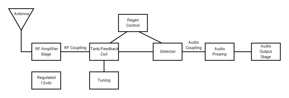
In recent blog posts I have made much mention of working out a design for a low voltage tube regen receiver. I have tried one experiment so far with a circuit for an RF amplifier stage that did not work out to my satisfaction. It’s clear that, to some small extent, one actually needs to know what one is doing to get these circuits to work. I have been studying from a good book for tube beginners, “Hollow State Design”, by Grayson Evans. I have been following though his design examples for grounded cathode and grounded grid amplifiers, and have absorbed enough to know
- the circuit I was trying clearly would not work, and
- I don’t understand enough yet to figure out what will work
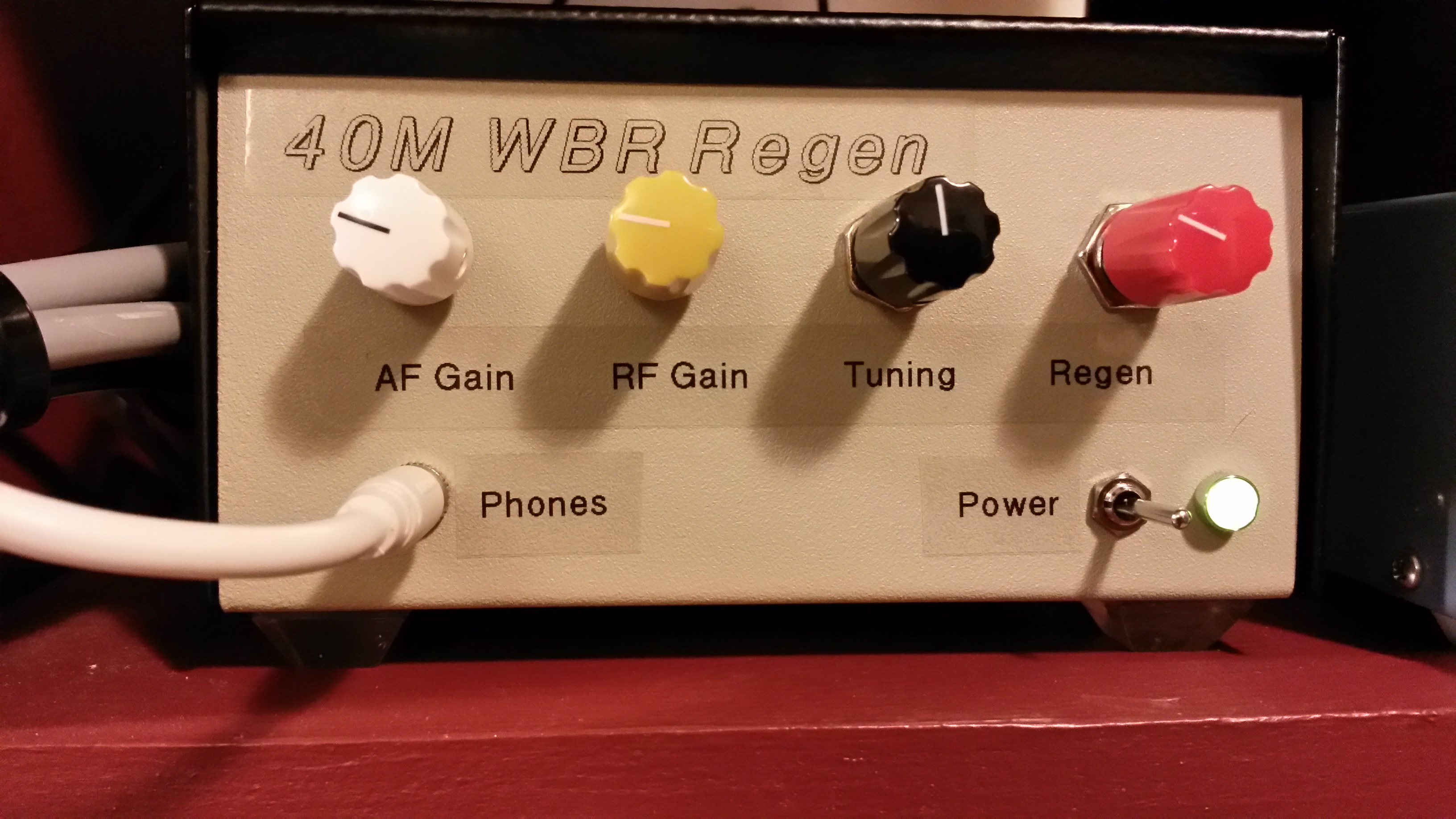
It’s interesting, and challenging, and I will get there eventually. In the mean time though I felt the strong desire to build something and get it working. Another small, solid-state QRP transmitter would be just the ticket. After the WBR regen building frenzy of a few weeks ago, I wound up with two WBRs – one on 40 meters, and one set up for 80 meters. The 40m WBR is part of the station setup with the two-tube transmitter right now. The 80m guy was just sitting on the shelf all alone. Although I don’t do much on 80 meters, I thought it would be cool to have a dedicated 80 meter transmitter to use with the WBR. Coincidently, I happened to have the makings of one sitting in a drawer.
A few weeks ago, while cruising around on eBay (like snacks, a frequent indoor winter time pitfall) I happened to come across an inexpensive kit for the “80 Meter Cubic Incher”
This was not a complete kit, just parts, a piece of PCB and some bits cut up for Manhattan style building and a photocopy of a the build article. The main attraction to me at the time was that the parts included a crystal on 3541, a frequency I don’t have in my collection. Also, a nice NPN RF transistor, a few toroids… looked like a good deal.
I’m not sure that at the time I bought it I planned to build it.
When the kit arrived I looked it over. Pretty minimal. The article was from “HF Radio Equipment ” magazine. (I have not been able to find any trace of this magazine on the web. It’s a mystery.) It referenced an original article in QST called the “Cubic Incher”. I searched and found two QST articles: the orignal in the July 1882 issue, and a later article in the September 1990 issue with enhancements including nicer keying and specifications for moving to different bands.

After reading through the photocopy and both QST articles, I decided this would make a very nice transmitter on 80 meters to use with the WBR.
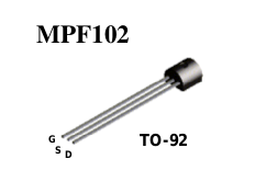
The primary attraction is that fancy RF transistor, a Motorola MRF472, that was actually designed to be used as a final in CB transmitters. It is reputed to be unkillable – withstanding infinite SWR if the supply voltage is 12v or less. I like that in a final. Also, the design puts out about 2 watts, which I consider a very robust, usable QRP signal. That’s only a half S-unit down from a full 5 watts, and a rock-crushing 9db up from the typical milliwatt rig. I had to build it.
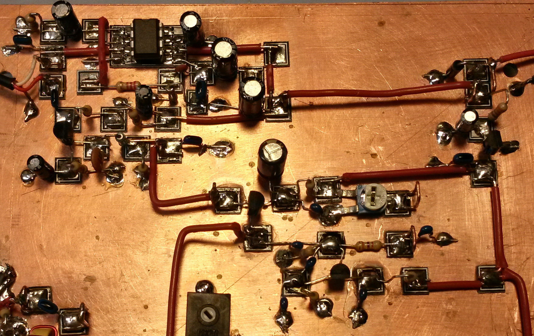
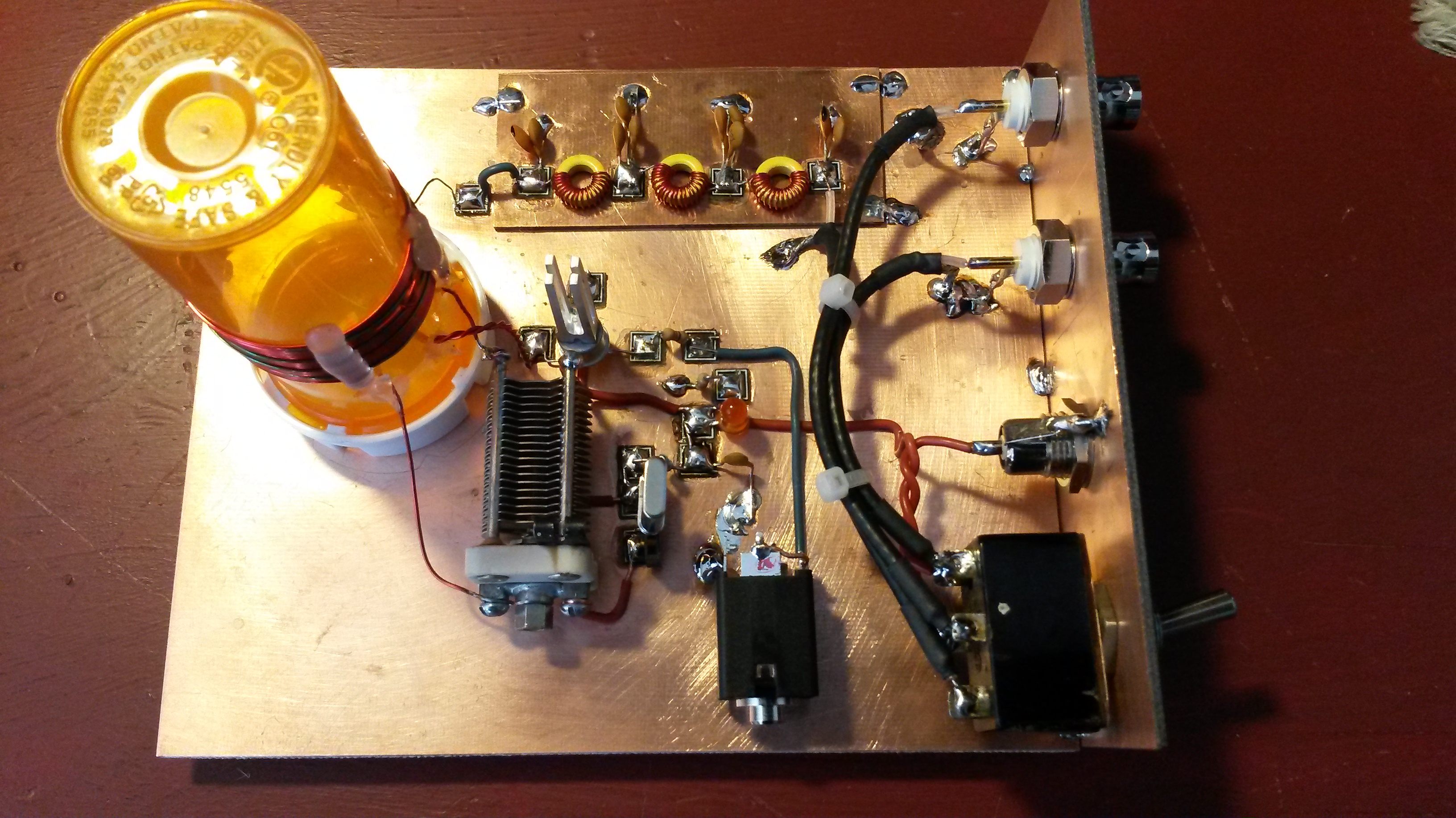
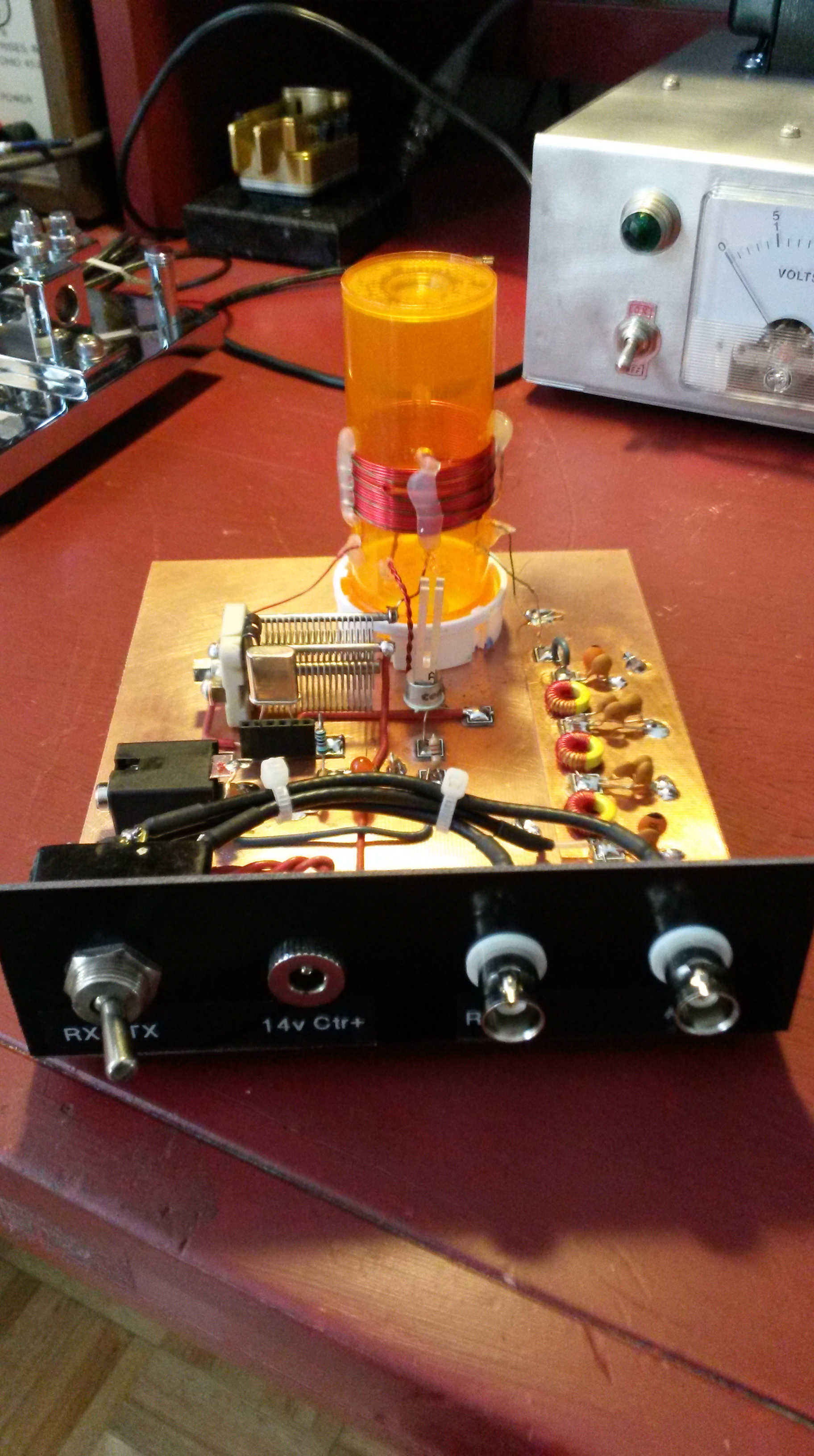
Now the other unusual attribute this transmitter possesses is that through the clever use of a double-wound transformer, it achieves oscillation with very few parts, and can be built into a box 1 inch by 1 inch by 1 inch (if you use the weird compression cap supplied) – hence the name “Cubic Incher”. As someone who can put his car keys down on an otherwise empty kitchen table and proceed to lose them for half an hour, the idea of a transmitter that small just doesn’t cut it, And I have cats, one cat in particular, who would delight in batting the thing irrevocably behind a radiator if it were that small. No way I was going that route. I gave it an entire 4 by 6 PCB board, and a robust recycled eBay variable cap weighing nearly a pound. And of course, little rubber feet.
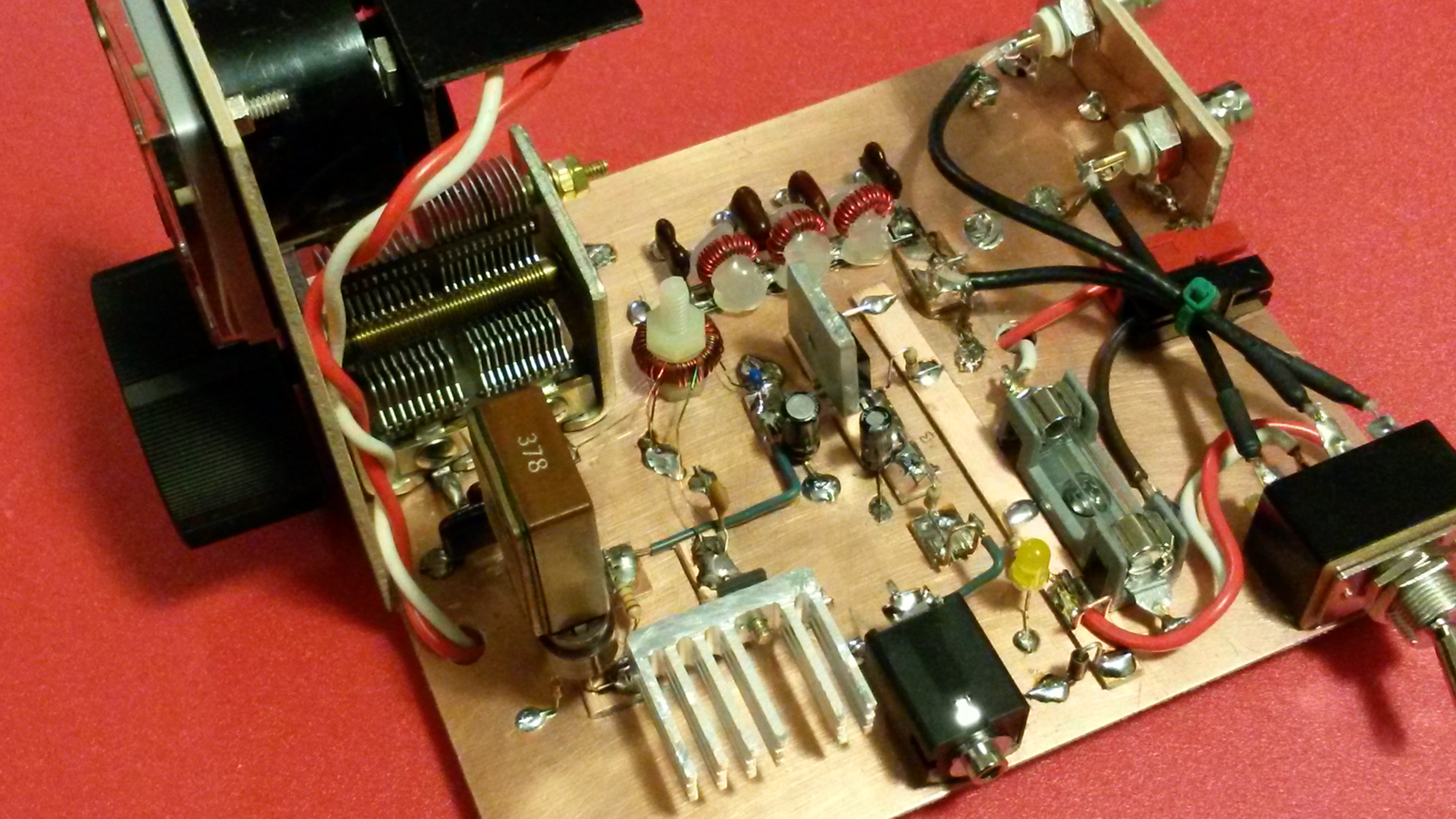
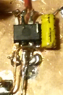
My somewhat larger than planned Cubic Incher. (Rubber feet not visible in this photo.)
One aspect of the Cubic Incher is that the crystal will oscillate over a wide range of loading capacitance, but tuning for “maximum smoke” is not necessarily best, as the keying may become chirpy at higher currents. The directions call for listening to the transmitted signal in a local receiver, and adjust the load for the best sounding signal. The rig draws about 15ma in its quiescent state, jumps to about 50ma when it starts to oscillate, and will continue to oscillate up to about 850ma, when it stops oscillating and becomes ominously silent.
Of course, tuning by ear works, but I decided it would be advantageous to have a current meter to monitor the draw. I happen to have in my junk box a small meter scavenged from a bit of vintage comm equipment, made by GE, that was just the right size. I’ve had it for years, unwilling to throw it away, but not having found a use for it. The face is marked with a linear scale from 0 – 100, perfect for a 1 amp meter. The question was how to shunt it correctly?
I never remember the “determine the internal resistance of the meter” drill and have to look it up every time I need it. I found an excellent web tutorial here. It turns out that my meter has an internal resistance of 1Kohm, and full scale deflection is 200mv. This made the maths easy: shunting it with 0.200 ohms would do the trick. I happened to have a bunch of 2.2 ohm 1/4 watt resistors on hand (from bipolar transistor biasing experiments on a rockmite) and 11 of them gave me the shunt I needed, more than adequate to dissipate the resulting current. I added a 1k, 10-turn pot for fine tuning, and the resulting meter works beautifully.
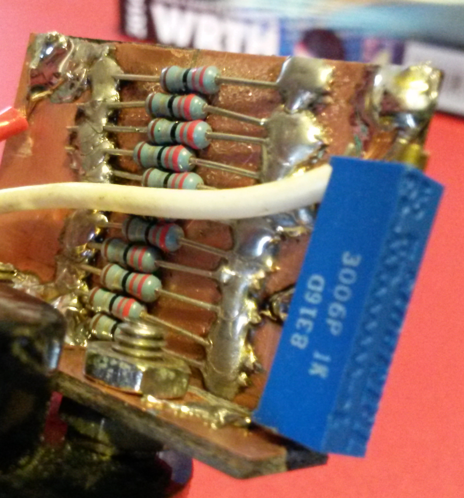
Shunt constructed to adjust full scale meter reading of 1 amp.
One other footnote on the meter. While fitting it to the front panel, it got stuck, and while trying to remove it the face plate flew off, bending the meter pointer. I was sure I had ruined it, but I bent the pointer back, and reassembled the face plate, it still worked. GE built these things tough back in the sixties.

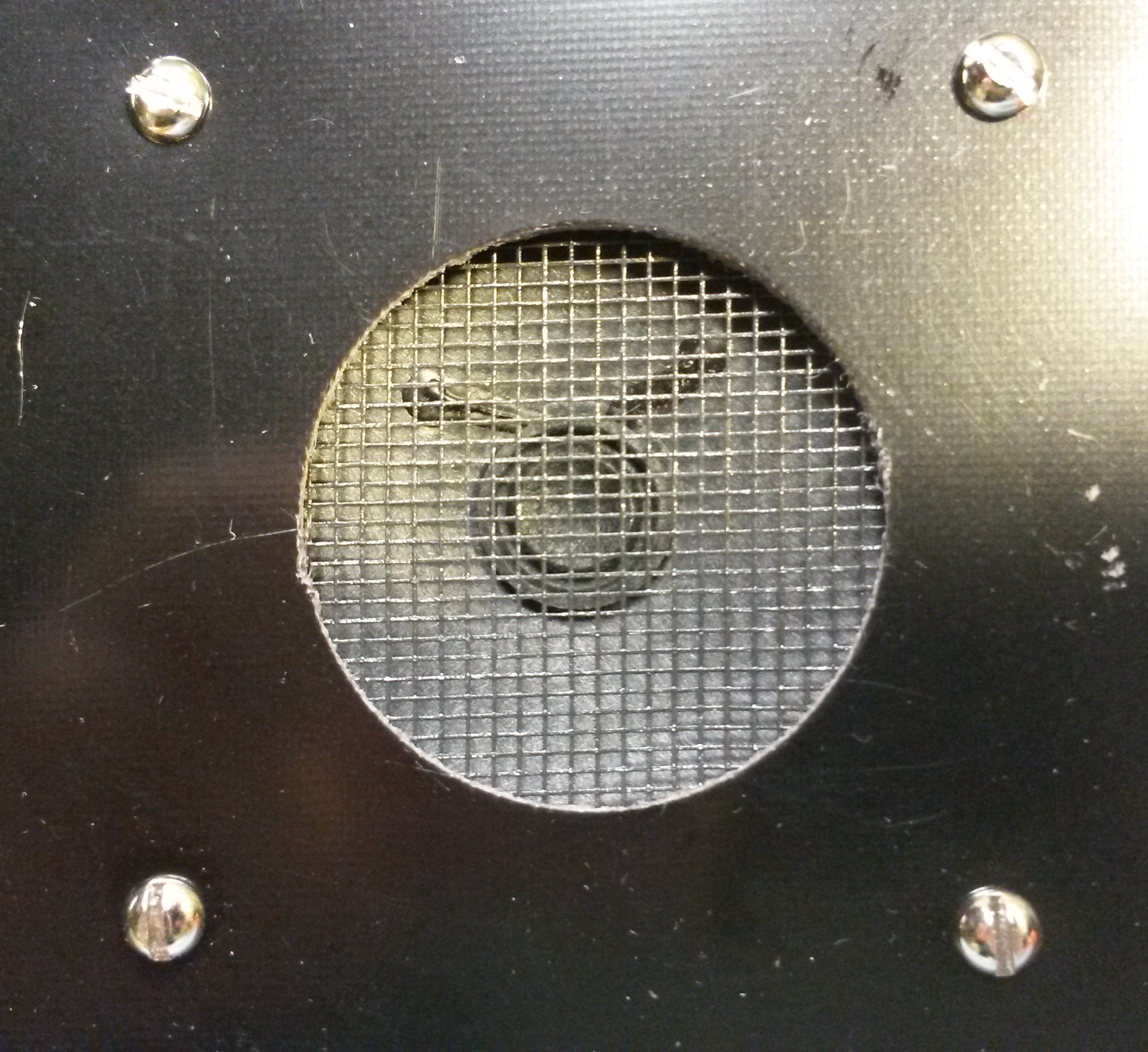
Meter in the Cubic Incher, reading 1 amp full scale.
With an entire 4 by 6 board to play with, I added a few amenities to my “Cubic Incher” not found in the original cramped edition:
- fused power connection with reverse polarity protection
- Anderson PowerPoles power connector ( I know this kind of obviates the need for the revere polarity protection, but hey, maybe someone wired the cable wrong…)
- custom heat sinks for the PA and keying transistor (keying for this rig is accomplished by switching the 12v supply with a PNP transistor. This transistor carries all of the current used by the rig, and could get warm in its own right.)
- Ft-243 crystal socket
- 7-pole low pass filter for output. This design comes from here.
- key socket
- non-QSK T-R switching, using a toggle switch. Low tech, but reliable.(I had someone ask why not use RF-sense to drive a relay. There is room, but I really dislike the chatter of the relay while sending.)
- little rubber feet
This is the first device I have built using Anderson PowerPoles for the power connector. I have been using them for years, but for some reason have stubbornly clung to coaxial power connectors on the device itself. Most of the ones I use are 5.5mm diameter, but some are 2.1mm centers and some are 2.5mm centers, and all of them are different lengths, resulting in dozens of almost interchangeable power cables littering the place. Also I am out of coaxial connectors, and they cost > $3 each at Mouser. No more! This all goes away using PowerPoles everywhere. Also, QSR now sells nice, bolt on polyethylene blocks which obviate the need for visible rectangular holes, a former impediment to using PowerPoles.
The heat sink for the final is made from a scrap cut from a computer processor heat sink. It gets slightly warm to the touch after keying a long string of CQs.
Heatsink on final transistor, made from a section of computer CPU heat sink.
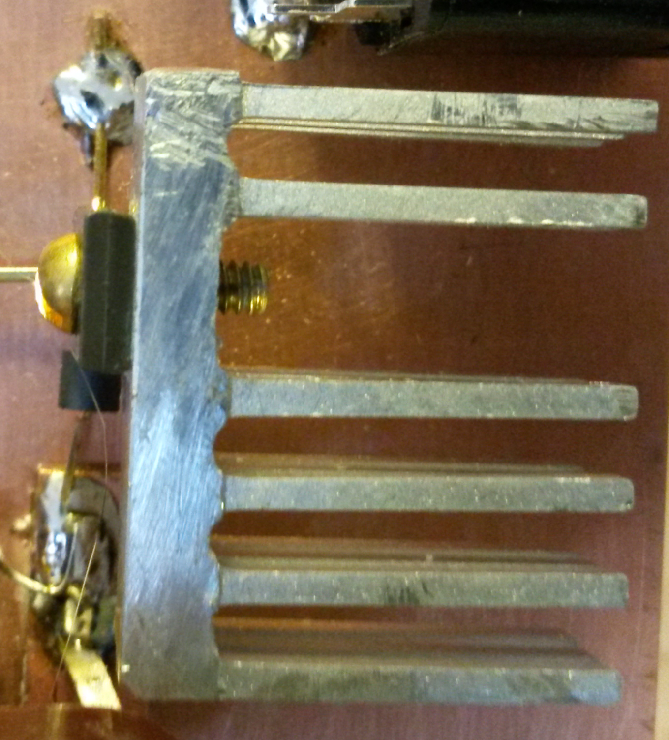
The one for the keying transistor is made from a bit of aluminum bar stock, and hardly gets warm at all.

Heat sink on keying transistor, made from a small section of aluminum bar stock.
The new transmitter plays pretty well. Loading it to 650ma, I am getting about 2.5 watts and nice sounding keying, using a vintage FT-243 crystal on 3580. With a modern HC-49 style crystal it loads up at around 20ma, and sounds okay, but it sounds better with the vintage rock.
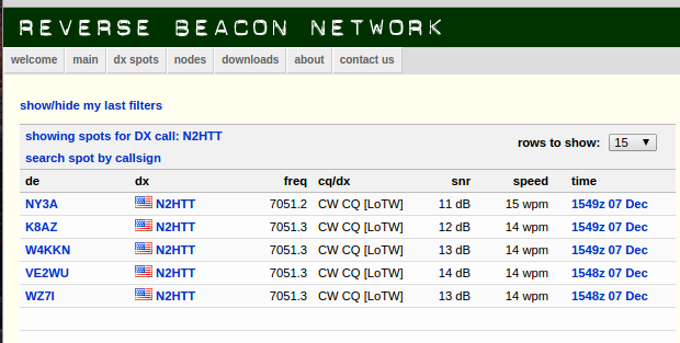
Using the toggle switch in conjunction with the antenna disconnect on the WBR, I was able to spot the signal with no difficulty at all. The 80 meter WBR doesn’t seem to overload as much as the 40m one while transmitting locally; I am actually getting a usable sidetone from the WBR while transmitting.
I’m quite pleased with this little transmitter. I will be trying it out on the air with the WBR, and will let you know if succeed in making that 100% home brew QSO.
73,
de N2HTT


